

Partitioned-cavity tunable fabry-perot filter
- Summary
- Abstract
- Description
- Claims
- Application Information
AI Technical Summary
Benefits of technology
Problems solved by technology
Method used
Image

Examples
Embodiment Construction
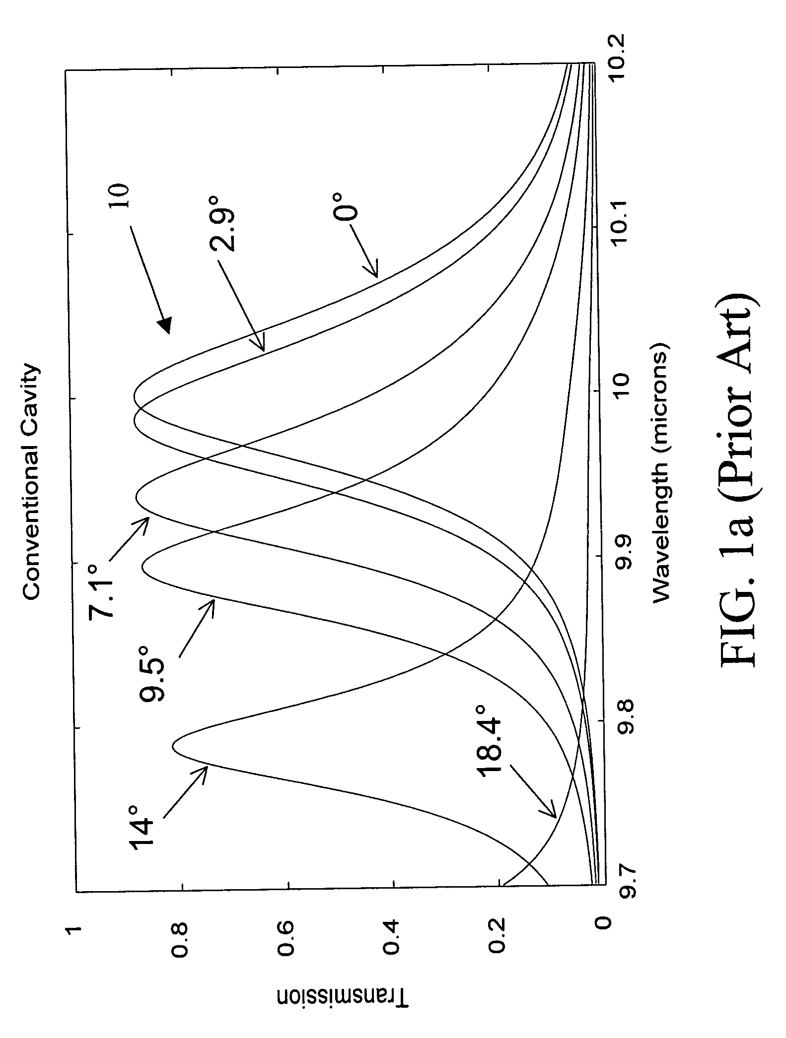
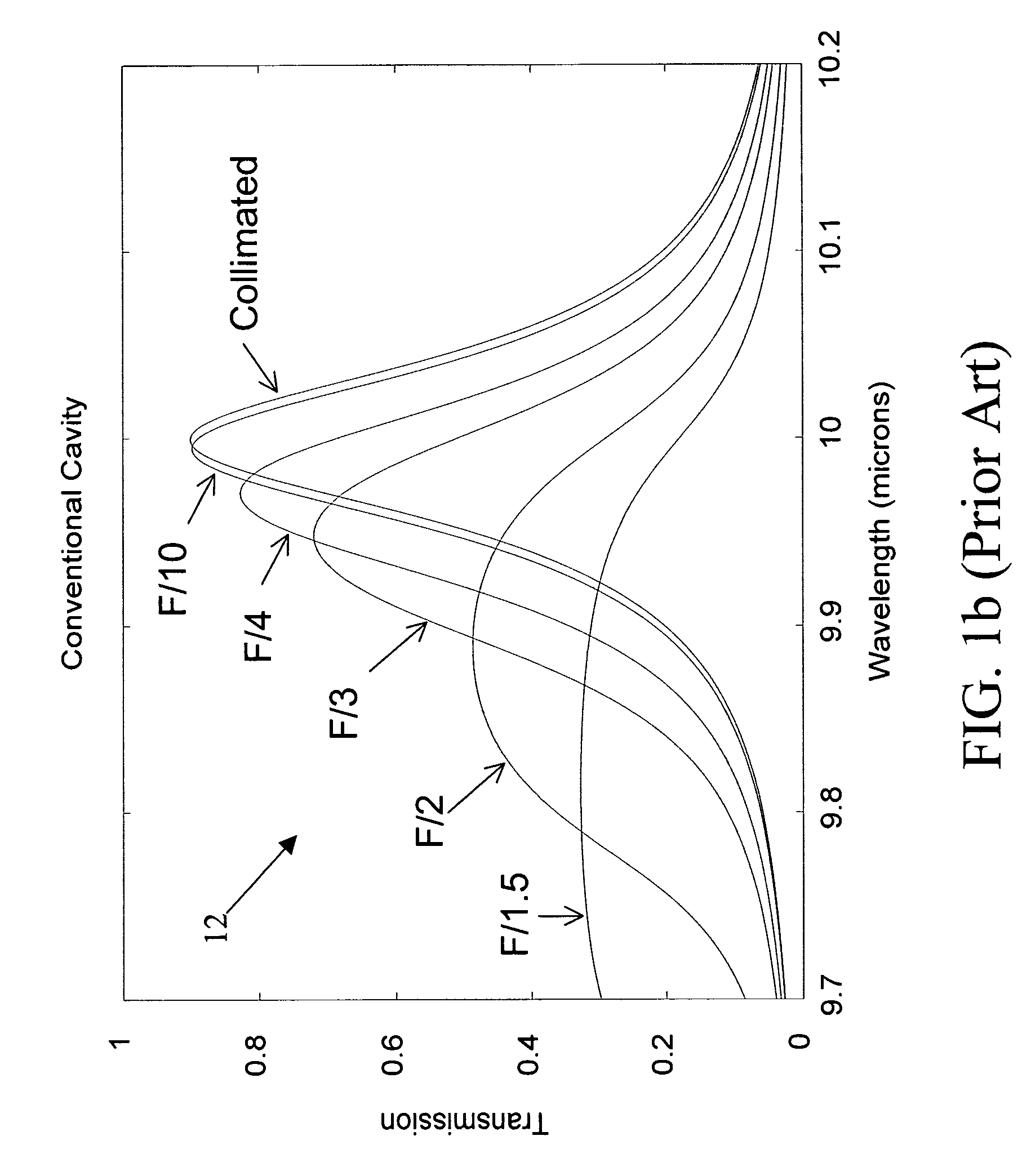
The present invention provides a tunable Fabry-Perot filter that is less sensitive to angle of incidence and thus suitable for use in optical imaging systems having lower f-number and hence greater light gathering power and smaller blur circle.
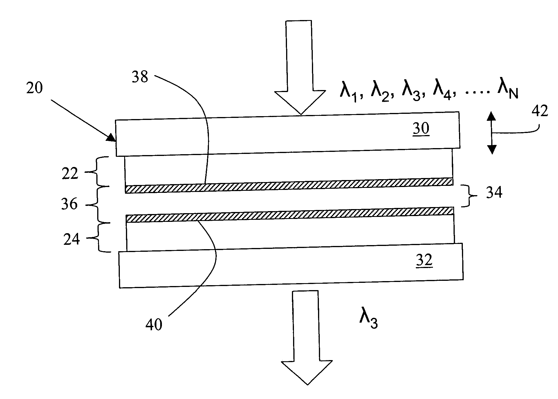
As shown in FIG. 2, a tunable Fabry-Perot filter 20 includes a pair of planar, parallel reflectors 22 and 24, typically multilayer dielectric, graded index or metallic films formed on transparent substrates 30 and 32, surrounding a variable air gap 34. The conventional air gap cavity is replaced with a partitioned cavity 36 that has an effective refractive index, neff that is greater than one (neff>1.0). The higher refractive index reduces the angle of the light ΘC within the cavity layer, which in turn reduces wavelength shift and spectral broadening.
The partitioned cavity 36 includes a pair of partitioned cavity dielectric layers 38 and 40 formed on the reflectors 22 and 24 on either side of variable air gap 34. Each of the partitioned ...
PUM
 Abstract
Description
Claims
Application Information