Fuel cell system

a fuel cell and system technology, applied in the field of fuel cell systems, to achieve the effect of preventing miniaturization and cost reduction, complicated control system, and complicated equipment configuration

Inactive Publication Date: 2005-03-31
HITACHI APPLIANCES INC
View PDF2 Cites 36 Cited by
  • Summary
  • Abstract
  • Description
  • Claims
  • Application Information

AI Technical Summary

Benefits of technology

[0010] First, three water pumps are required for controlling the flow rate of the liquid media that is being circulated for cooling the stack or performing heat exchange with the stack; therefore, the configuration of the equipment is complicated, and miniaturization and cost reduction are prevented.
[0011] Second, since detection and control of the temperature for each flow control is performed independently, when the rate of flow through a pump is changed to maintain a desired condition, the temperature condition of the flow has an effect on the heat exchange condition of the heat exchanger on the downstream side, and thus control of the rate of flow through the other pump is necessary. Therefore, the control system is complicated.

Problems solved by technology

First, it is required to recover the heat generated in the power generation efficiently.
However, the following problems occur.

Method used


Image

  • Fuel cell system
  • Fuel cell system
  • Fuel cell system

Examples


Embodiment Construction

[0022] Embodiments of a fuel cell system according to the present invention will be described with reference to the accompanying drawings.

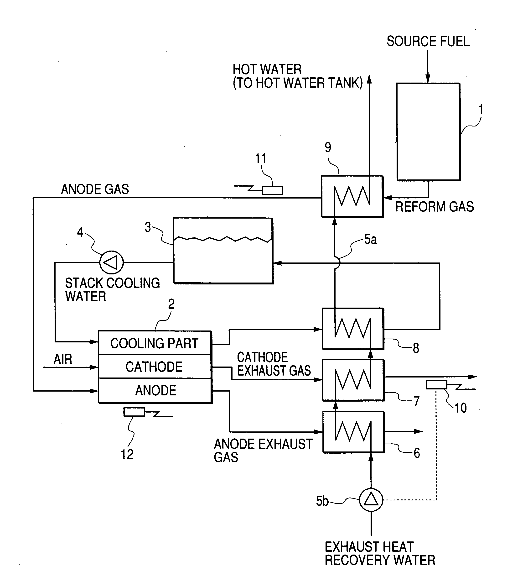
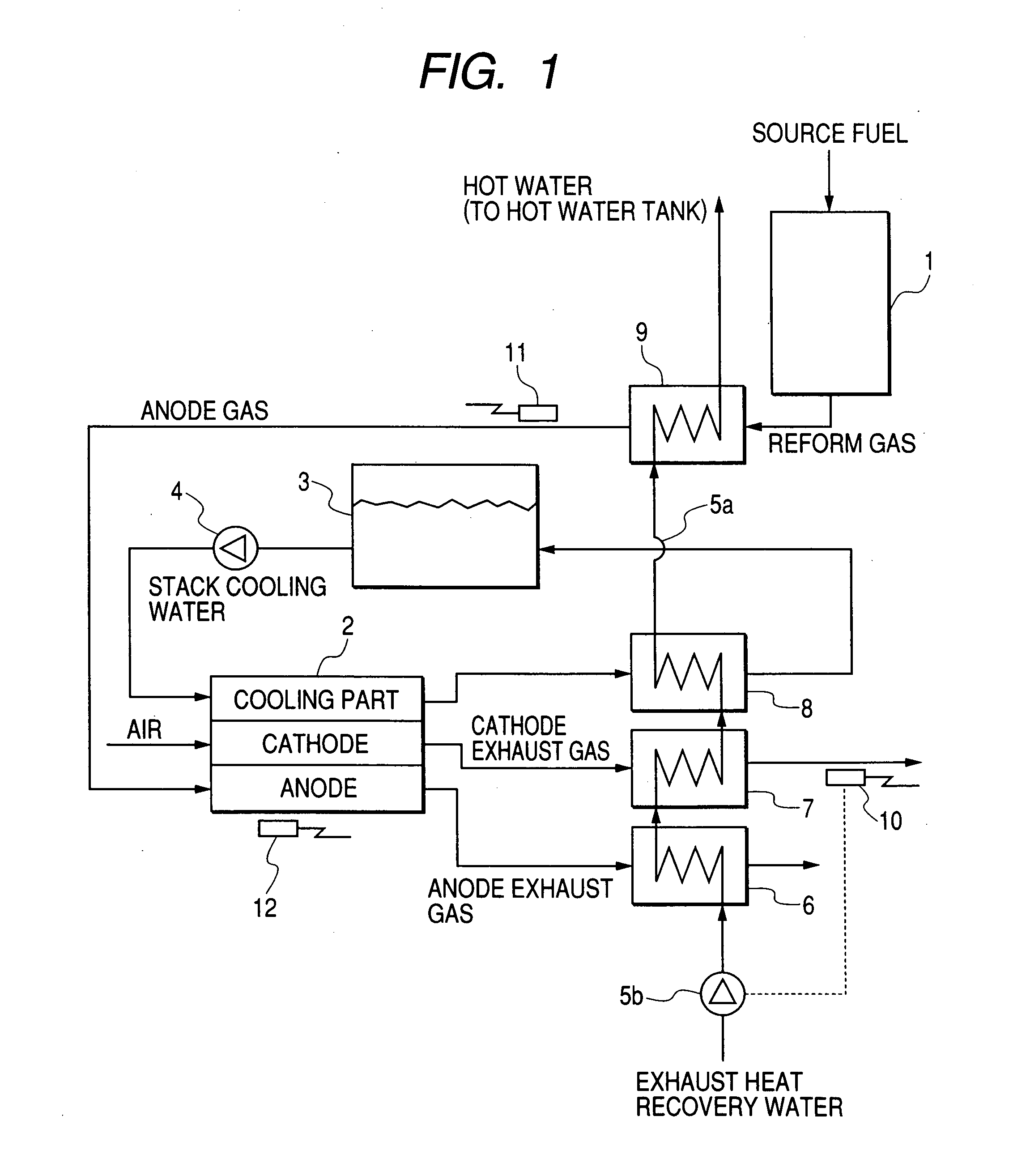
[0023]FIG. 1 shows an example of a fuel cell cogeneration system according to the present invention. A reformer 1 is supplied with city gas or propane gas, which serves as a source fuel. Hydrogen rich gas which serves as a reform gas is obtained from the source fuel. The hydrogen rich gas is supplied to the anode of a fuel cell stack 2 as anode gas. On the other hand, air is supplied to the cathode of the fuel cell stack 2 as cathode gas by a blower (not shown). To cool the fuel cell stack 2, a cooling tank 3 and a cooling pump 4 are provided. The stack cooling water is supplied to a cooling part of the fuel cell stack 2, and it circulates between the cooling tank 3 and the cooling part of the fuel cell stack 2.

[0024] From the anode and cathode of the fuel cell stack 2, the anode exhaust gas and the cathode exhaust gas, respectively, are dischar...


PUM

PropertyMeasurementUnit
temperatureaaaaaaaaaa

Abstract

A stack that is supplied with reform gas containing hydrogen that is produced by a reformer by reforming source fuel to serve as anode gas and air containing oxygen to serve as cathode gas, and it performs power generation. The stack has a circulation channel for stack cooling water through which the stack cooling water flows for maintaining he temperature of the stack. There is a first heat exchanger that performs heat exchange between anode exhaust gas and exhaust gas recovery water; a second heat exchanger that performs heat exchange between cathode exhaust gas and the exhaust gas recovery water; a third heat exchanger that performs heat exchange between the stack cooling water and the exhaust gas recovery water; and a fourth heat exchanger that performs heat exchange between the reform gas and the exhaust gas recovery water. These heat exchangers are disposed in series in a channel of the exhaust heat recovery water.

Description

BACKGROUND OF THE INVENTION [0001] The present invention relates to a fuel cell system. [0002] The fuel cell system reforms source fuel, such as city gas and propane gas, in a reformer; supplies a hydrogen rich gas obtained from the reformer to a fuel cell stack; and makes the hydrogen rich gas react with oxygen in air, thereby performing power generation. A fuel cell cogeneration system recovers heat generated in the course of power generation and stores it as hot water, and the hot water is supplied to a hot-water supply or is used for heating the home. [0003] An example of a conventional layout of an exhaust heat recovery system and the heat exchangers used therein is described in JP-A-2003-217620. FIG. 4 shows a block diagram of such a layout. [0004] In the system of FIG. 4, a heat exchanger 6 is provided to exchange heat between exhaust gas from the anode (anode exhaust gas) and exhaust heat recovery water, and a heat exchanger 15 is provided to exchange heat between exhaust ga...

Claims


Application Information

Patent Timeline
Patent Type & Authority Applications(United States)
IPC IPC(8): H01M8/00H01M8/04H01M8/06
CPCH01M8/04029H01M8/04156H01M8/04328Y02E60/50H01M8/04365H01M8/04768H01M8/0612H01M8/0435
Inventor ENOKIZU, YUTAKASAKAMOTO, KOICHI
Owner HITACHI APPLIANCES INC
Why Eureka
Try Eureka