Microelectronic cell electroporation array

a microelectronic cell and array technology, applied in the field of electroporation, can solve the problems of multifactoriality of most diseases, increasing the search volume, and becoming more eviden

Inactive Publication Date: 2005-03-31
THE GOVERNMENT OF THE UNITED STATES OF AMERICA AS REPRESENTED BY THE SEC OF THE NAVY NAVAL RES LAB WASHINGTON
View PDF11 Cites 22 Cited by
  • Summary
  • Abstract
  • Description
  • Claims
  • Application Information

AI Technical Summary

Benefits of technology

[0014] Another objective for the present invention would be the study of biologic or chemical agents. Biological or chemical agents expected to be hazardous could be perfused over the cells and their uptake into the cells accelerated or increased to allow the observation of the effect of low concentrations of the agents.

Problems solved by technology

The problem is with the magnitude of the search; typically there are 1000 to 100,000 base pairs within a given gene.
Another problem becoming more evident is the fact that most diseases are multifactorial or result from a number of gene “defects”.
In addition, most current techniques for inserting genes into cells to study their benefit or detriment do not lend themselves to rapid parallel study.
The problem with the prior art in this field is the lack of a high-density electrode array for electroporating, a method to hold cells safely in contact with the array and a method to put a variety of genes in contact with the cells for electroporating.
The disadvantages compared to our invention are; a higher volume of costly gene or drug solution will be required, imaging all the cells at one time is difficult, large arrays with 3000 or more discrete experiment sites are difficult to design and use efficiently and it is not possible to study cells electroporated with different genes in one chamber.
None of the above devices are for flowing different solutions carrying different genes, drugs etc for electroporation of stationary cells.

Method used


Image

  • Microelectronic cell electroporation array
  • Microelectronic cell electroporation array
  • Microelectronic cell electroporation array

Examples


Embodiment Construction

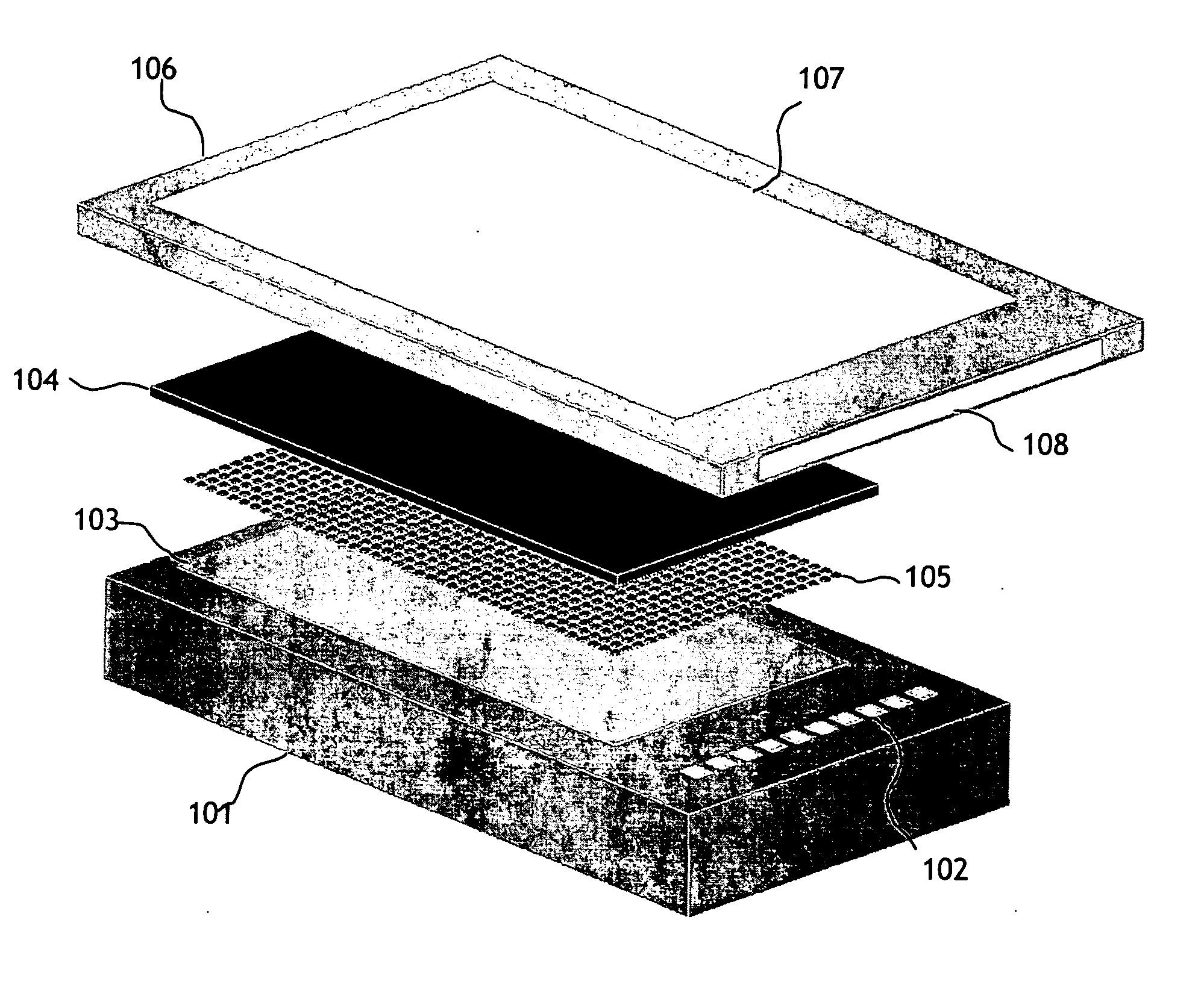
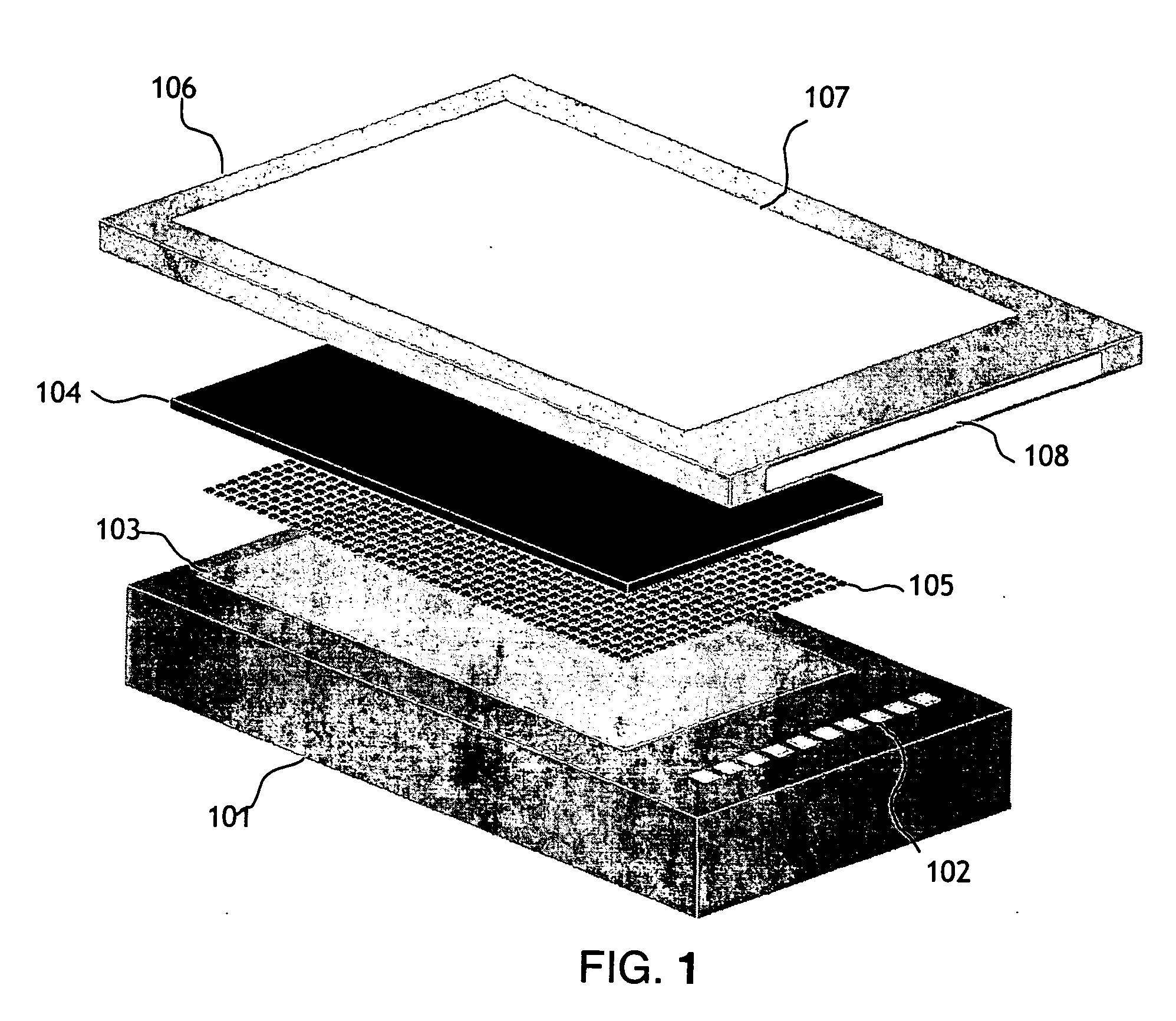
[0025] The present invention, shown in FIG. 1, has 3 primary components; a microelectronic stimulator array (101), a conducting electrode material (104) which the cells or tissue are cultured on and a fluid flow chamber (106) and apparatus to control the solutions of genes, gene silencing RNAi, gene inhibition agents, drugs or other substances to be presented for entry into the cells. The timing of the fluid flow and the active areas of the stimulator array will be controlled via a computer interface.

[0026] The microelectronic silicon stimulator chip (101) has 10 bond pads (102) which are connected to the power supply, clocks, biases and data I / O. The chip also has an active area (103) which has a number of vias which are connected to the microwire glass electrode (104) with indium bump bonds (105). The flow chamber (106) is attached above the microwire glass electrode. The chamber has an optical window on the top (107) (that can be coated with a transparent electrode material, suc...


PUM

PropertyMeasurementUnit
diameteraaaaaaaaaa
cellular transmembrane voltageaaaaaaaaaa
transmembrane voltagesaaaaaaaaaa

Abstract

The electroporation array is comprised of three technologies: microwire glass electrodes, microelectronic multiplexer stimulator chips and microfluidic flow chamber. Various substances, such as genes, gene silencing RNAi, gene inhibition agents or drugs, can be perfused into the microfluidic flow chamber. The entry of the various substances into the cells will be facilitated by electroporation. An applied electric potential causes nanoscale pores to open in the cell membrane allowing substances in the solution to freely diffuse into the cell. The specific cells selected for electroporation are defined using the computer controlled microelectronic stimulator array. An “image” of which electrodes within the array to apply the electric potential to, and thus electroporate, is de-multiplexed onto the array. All the selected electrodes deliver a current pulse varied by the intensity of the de-multiplexed “image”. By serially perfusing different substances across the cells or tissue and electroporating different areas of the cell or tissue culture, it will be possible to have different cells within the culture contain different genes, gene silencing RNAi, gene inhibition agents, drugs, chemicals or other substances or sets thereof. It is also possible to re-electroporate subsets of cells on the array to allow for multiple gene combinations. In essence, this invention allows for the creation of cell arrays and would be analogous to gene arrays, which have been so important in recent advances in biotechnology, such as the human genome project.

Description

BACKGROUND [0001] The present invention deals generally with electroporation, specifically the concept of spatially targeted entry of genes, drugs, chemicals and other substances into cells with a microelectronic electroporation array. [0002] Gene therapy is an experimental method that attempts to replace, manipulate, or supplement nonfunctional or malfunctioning genes in cells with other genes to cure disease. The disease is generally one in which the patient's version of the gene is significantly different from that found the general population. As a preliminary step in studying a candidate gene to be used for therapy, that gene may be inserted into cells of the type involved in the disease. If the candidate gene alleviates the cellular component of the disease it may be studied further in vivo in an animal model of the disease. In some cases it is not known what the exact difference in the disease gene is or even which gene within a chromosome is related to the disease. In this c...

Claims


Application Information

Patent Timeline
Patent Type & Authority Applications(United States)
IPC IPC(8): C12N15/87
CPCC12N15/87C12M35/02Y10S435/817
Inventor JOHNSON, LEESCRIBNER, DEANPANCRAZIO, JOSEPH
Owner THE GOVERNMENT OF THE UNITED STATES OF AMERICA AS REPRESENTED BY THE SEC OF THE NAVY NAVAL RES LAB WASHINGTON
Why Eureka
Try Eureka