
System and method for servicing communications using both fixed and mobile wirless networks

a fixed and mobile network technology, applied in data switching networks, power management, high-level techniques, etc., can solve the problems of reducing the usefulness of these devices, consuming far more power, and devices that cannot use bluetooth® to access network resources in a mobile environment that extends beyond the short range of their range, so as to achieve the effect of greatly reducing the power consumption of mobile devices

Active Publication Date: 2005-03-31
AVAGO TECH INT SALES PTE LTD
View PDF5 Cites 71 Cited by
  • Summary
  • Abstract
  • Description
  • Claims
  • Application Information

AI Technical Summary

Benefits of technology

[0007] This disclosure teaches mobile device(s) that may be located within a vehicle or other mobile platform. The mobile devices interface to a mobile wireless network within the vehicle. A relay routes communications from the mobile device to a wide area wireless network such as cellular network or satellite network. This allows the power consumption of the mobile device to be greatly reduced as the mobile device need only communicate with the local intra-vehicular WLAN. The vehicle services as the power supply for the relay.
[0008] When the coverage area of the intra-vehicular WLAN overlaps that of another WLAN, a seamless handoff allows continuous data or voice connectivity between the overlapping wireless networks. Thus, a Bluetooth® equipped voice handset phone can safely range between a premises-based network(s) and mobile vehicle network(s) without negatively impacting data connectivity.
[0009] This disclosure more specifically teaches that Bluetooth® enabled wireless devices may roam between WLANs that support Bluetooth® voice and / or data communications by establishing parallel communication pathways between the Bluetooth® enabled wireless terminal and overlapping Bluetooth® enabled WLANs. In one example, a first WLAN is fixed to a physical location while a second WLAN has mobile APs. The second WLAN communicatively couples to a WAN such as a cellular satellite network. Parallel communications are established, and handoff criteria govern seamlessly switching communications between the WLANs in order to avoid any lost or dropped communications.
[0010] Another embodiment provides the mobile network relay device itself. This mobile network relay device has a first wireless interface operable to communicate with the wireless device over an intra-vehicular WLAN. A second wireless interface communicatively couples to an extravehicular wireless network. The mobile network relay device routes communications between the first wireless interface and the second wireless interface and thus between the wireless device and the extravehicular wireless WAN. This arrangement allows the power consumption requirements of the wireless device to be reduced as this burden shifts to the mobile network relay. The intra-vehicular WLAN is typically a low-power, short-range, digital radio network such as Bluetooth® or another like network. The extravehicular network(s) typically are cellular, satellite, or other like network(s) known to those skilled in the art.
[0014] Additionally, the wireless device may have the internal ability to communicate over Bluetooth®, 802.11, cellular, satellite or other like networks. Here, internal processors choose which network is to be used to balance the signal quality, transmission cost, and power consumption. Furthermore, these internal or external abilities, when coupled to a mobile relay, allow the mobile device to range between a first premises based WLAN and a second premises based WLAN that have non-contiguous service coverage areas.

Problems solved by technology

However, these devices cannot use the Bluetooth® protocol to access network resources in a mobile environment that extends beyond the short range of their digital radio systems.
Thus, most mobile systems rely on wider range cell networks that consume far more power than Bluetooth® systems.
This higher level of power consumption reduces the usefulness of these devices by negatively impacting the battery life of the device.

Method used


Image

  • System and method for servicing communications using both fixed and mobile wirless networks
  • System and method for servicing communications using both fixed and mobile wirless networks
  • System and method for servicing communications using both fixed and mobile wirless networks

Examples


Embodiment Construction

[0028] Preferred embodiments of the present invention are illustrated in the FIGs, like numerals being used to refer to like and corresponding parts of the various drawings.

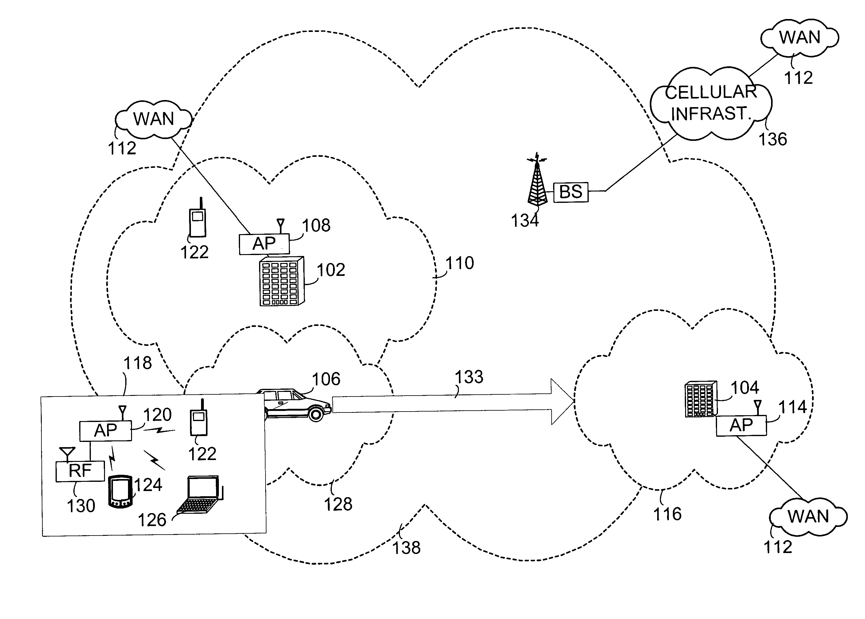
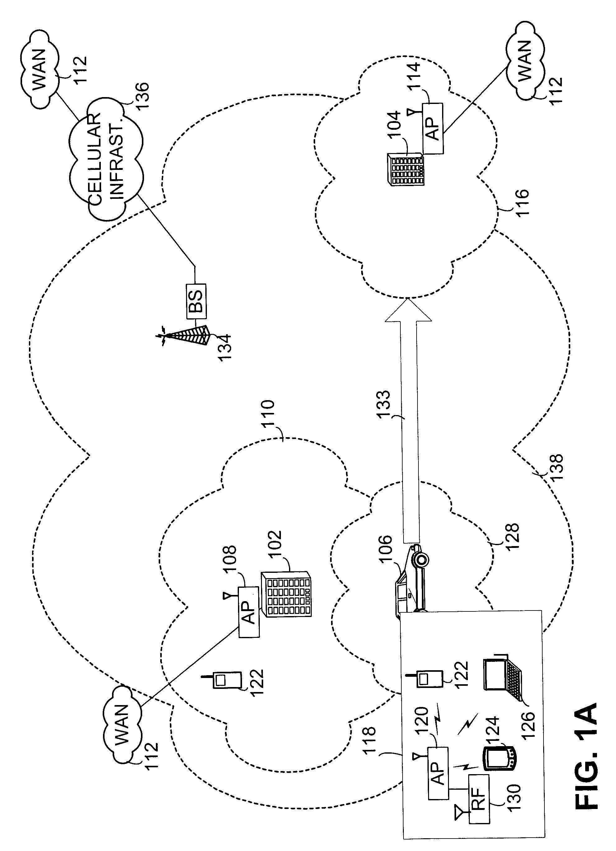
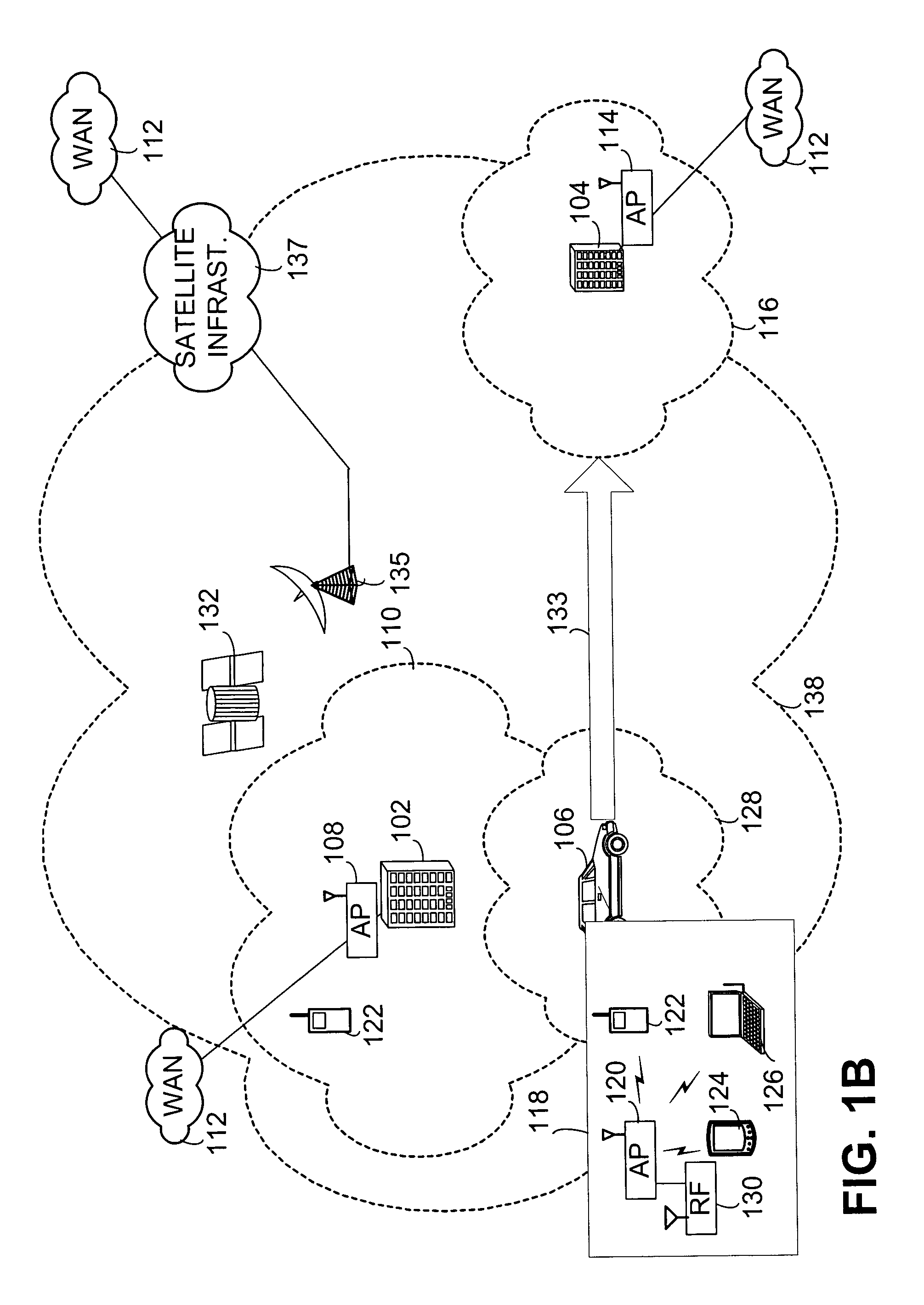
[0029]FIG. 1A provides a system overview in which WLANs serve fixed locations, such as those tied to building 102 and building 104, and mobile locations such as vehicle 106. Building 102 has at least one Wireless Access Point (AP) 108 which enables Personal Data Assistants (PDAs), telephone handsets, laptops, mobile computing devices and other wireless devices to interface with WLAN 110. This WLAN may connect to Wide Area Network (WAN) 112 such as the Internet or other like WANs known to those skilled in the art. Similarly, building 104 has AP 114 used to serve wireless devices within coverage area 116. As shown in callout 118, a wireless AP 120 within vehicle 106 may serve wireless handset 122, PDA 124, laptop 126 or other wireless devices as known to those skilled in the art. The coverage area of WLAN 128 serv...


PUM


Abstract

Mobile wireless device(s) roam within and between premises and a vehicle or other mobile platform and interface to wireless local area networks within the premises or vehicle. When using the intra-vehicular network, a communication relay within the vehicle routes communications from the wireless device to a wide area wireless network such as cellular network or satellite network. This allows the power consumption of the mobile wireless device to be greatly reduced as the mobile device need only communicate with the local intra-vehicular WLAN. The vehicle acts as the power supply for the relay. When the coverage area of the intra-vehicular WLAN overlaps that of another WLAN, seamless handoff allows continuous data or voice connectivity between the overlapping wireless networks.

Description

TECHNICAL FIELD [0001] The present invention relates generally to mobile wireless devices, and more particularly to a mobile network relay device that allows wireless communication devices adapted to a first local wireless network to interface with a second wireless network. BACKGROUND OF THE INVENTION [0002] Communication technologies that network electronic devices are well known. Examples of those technologies include: wired packet data networks; wireless packet data networks; wired telephone networks; and satellite communication networks, among others. These communication networks typically include a network infrastructure that services a plurality of client devices. The Public Switched Telephone Network (PSTN) is probably the best-known communication network and has been in existence for many years. The Internet, another well-known example of a communication network, has also been in existence for a number of years. Communication networks like these enable client devices to com...

Claims


Application Information

Patent Timeline
IPC IPC(8): H04L12/28H04L12/56H04M1/72412H04M1/73H04W84/12H04W88/04H04W88/06H04W88/16H04W92/02
CPCH04M1/7253H04M2250/02H04W52/0229H04W52/0274H04W92/02H04W88/04H04W88/06H04W88/16H04W84/12Y02D30/70H04M1/72412
Inventor MORTON, PAUL
Owner AVAGO TECH INT SALES PTE LTD
Learn More