
Calibration method and radio apparatus

Inactive Publication Date: 2005-03-31
PANASONIC INTELLECTUAL PROPERTY CORP OF AMERICA
View PDF1 Cites 31 Cited by
  • Summary
  • Abstract
  • Description
  • Claims
  • Application Information

AI Technical Summary

Benefits of technology

By employing the above apparatus, the electric power of received signals becomes small if signals are transmitted after the weighting factors rotated by the rotation amount of an incorrectly set correction value, so that the rotation amount of a correct correction value can be estimated accurately.

Problems solved by technology

In such cases, even if the weights generated based on the received signals are implemented into signals to be transmitted, there will not be formed the weights for transmission that reflect the values of appropriate weights, so that the transmission beams therefor cannot be controlled normally.

Method used


Image

  • Calibration method and radio apparatus
  • Calibration method and radio apparatus
  • Calibration method and radio apparatus

Examples


first embodiment

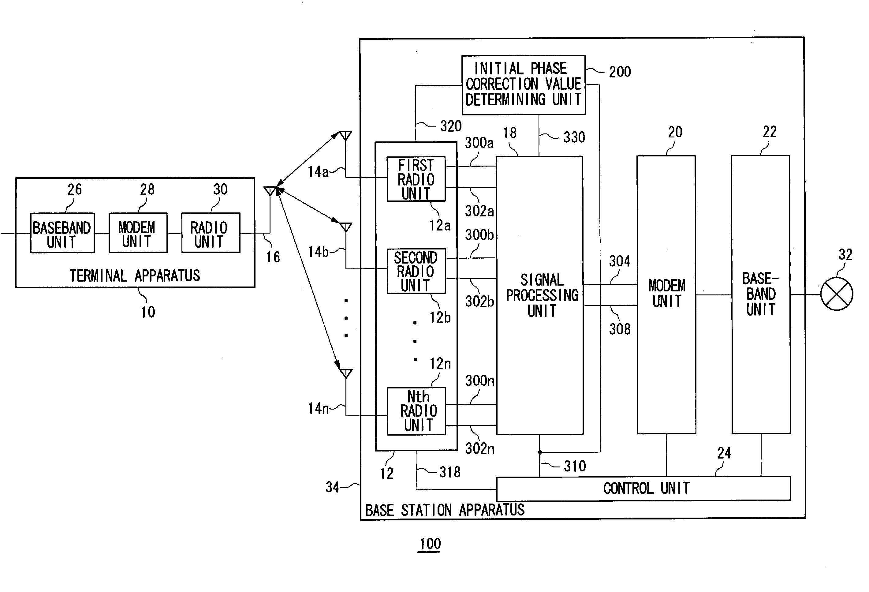
Before describing specific modes of invention, a general description of the present invention will be given hereinbelow. A first embodiment according to the present invention relates to a base station apparatus, to which terminal apparatuses can be connected, such as a base station apparatus used in the wireless LAN (Local Area Network). A base station apparatus according to the present embodiments is provided with a plurality of antennas and also provided with a plurality of quadrature detectors and a plurality of quadrature modulators. The quadrature detector and the quadrature modulator have each a phase shifter whose phase is indefinite at the time of power-on. The base station apparatus according to the present embodiments corrects phase errors of the quadrature detector and the quadrature modulator. Signals are transmitted from one of the plurality of antennas (hereinafter this antenna as well as a transmitting / receiving apparatus connected to this antenna will be referred to...

second embodiment

Similar to the first embodiment, a second embodiment of the present invention relates to a base station apparatus for correcting errors in initial phases between an quadrature detector and an quadrature modulator. In this second embodiment, an antenna for measurement is provided for exclusive use separately from an antenna used in communication. A signal generator and a measuring unit for level measurement are also connected to the antenna for measurement.

FIG. 11 illustrates a structure of a base station apparatus 34 according to the second embodiment. The base station apparatus 34 includes, similar to the base station apparatus of FIG. 1, basestation antennas 14, radio units 12, a signal processing unit 18, a modem unit 20, a baseband unit 22, a control unit 24 and an initial phase correction value determining unit 200, and includes, different form the base station apparatus of FIG. 1, a measuring antenna 230, a switch unit 140, a frequency conversion unit 146, a transmitter 144 ...


PUM


Abstract

A signal processing unit carries out signal processings necessary for a receiving / transmission processing of an adaptive array antenna. The signal processing unit also carries out a signal processing necessary for determining phase errors in quadrature modulation and quadrature detection to be done by radio units, namely, for determining a rotation amount of an initial phase correction value. The radio units in a base station apparatus carry out frequency conversion processing, amplification processing, quadrature modulation processing, quadarture detection processing, A-D or D-A conversion processing and the like between the baseband signals and radio frequency signals. An initial phase correction value determining unit determines rotation amounts of initial phase correction values, based on power-measuring received signals inputted from the radio units, and outputs to the signal processing unit as initial phase correction value signals.

Description

BACKGROUND OF THE INVENTION 1. Field of the Invention The present invention relates to calibration technologies and it particularly relates to a calibration method and a radio apparatus utilizing the same in adaptive array antennas. 2. Description of the Related Art In wireless communication, it is generally desired that the limited frequency resources be used effectively. Adaptive array antenna technology is one of the technologies that can realize effective utilization of frequency resources. In adaptive array antenna technology, the amplitude and phase of signals transmitted and received by a plurality of antennas, respectively, are so controlled as to form a directional pattern of the antenna. In other words, the apparatuses provided with adaptive array antennas change the amplitude and phase of signals received by a plurality of antennas, respectively, add up the thus changed received signals, and receive the signals equivalent to the signals received by the antenna having ...

Claims


Application Information

Patent Timeline
IPC IPC(8): H01Q3/24H01Q3/26H04B1/10H04B7/06H04B7/08H04B7/10H04M1/00
CPCH04B7/0613H01Q3/267
Inventor DOI, YOSHIHARU
Owner PANASONIC INTELLECTUAL PROPERTY CORP OF AMERICA
Learn More