Method and apparatus for treating liquid waste

a technology of liquid waste and treatment method, applied in lighting and heating apparatus, combustion types, heat recovery, etc., can solve the problem of destroying any hazardous or toxic constituency of waste material

Inactive Publication Date: 2005-03-31
PEAT INT INC
View PDF46 Cites 31 Cited by
  • Summary
  • Abstract
  • Description
  • Claims
  • Application Information

AI Technical Summary

Problems solved by technology

This dissociation destroys any hazardous or toxic constituency of the waste material.

Method used


Image

  • Method and apparatus for treating liquid waste
  • Method and apparatus for treating liquid waste
  • Method and apparatus for treating liquid waste

Examples


Embodiment Construction

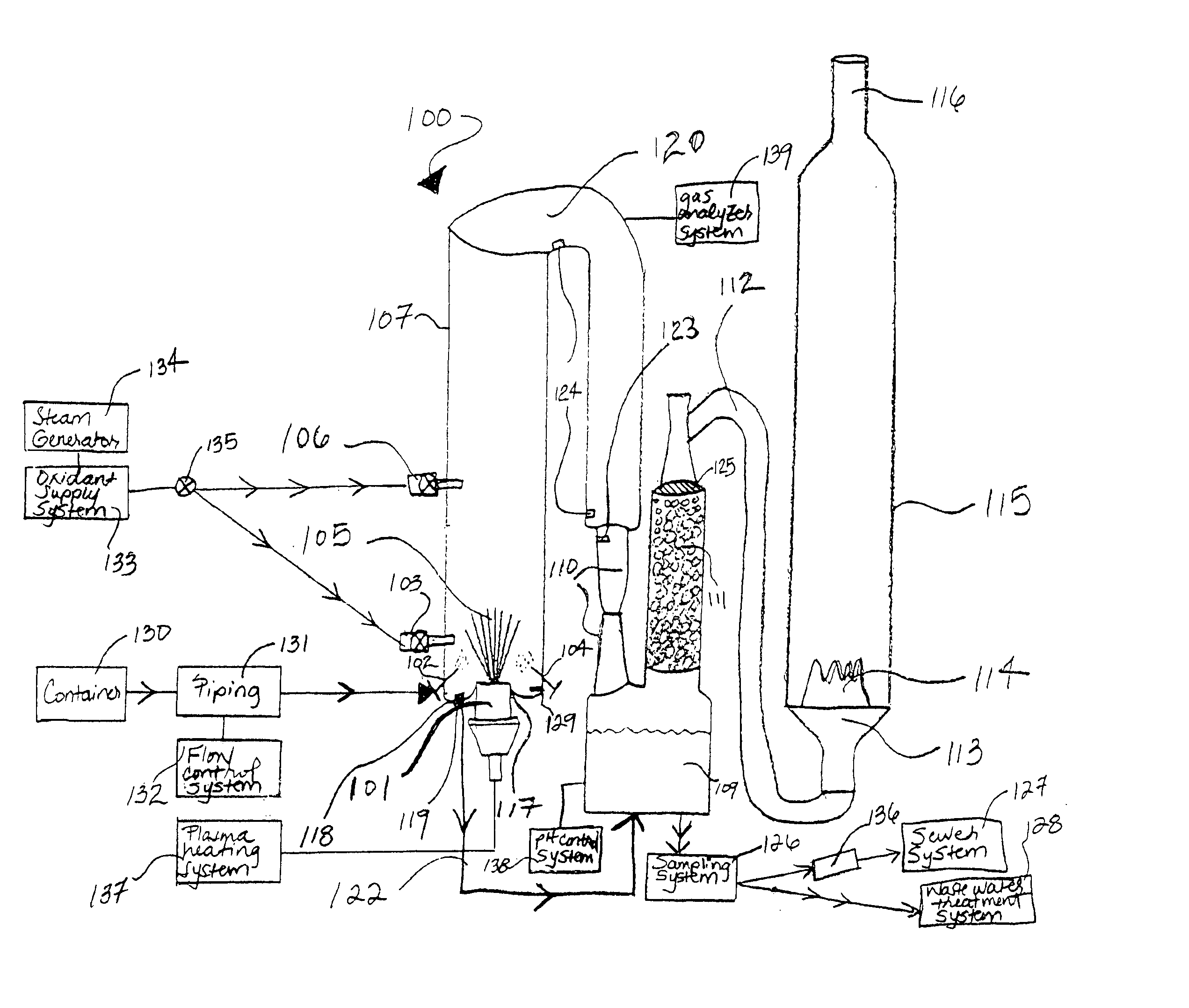
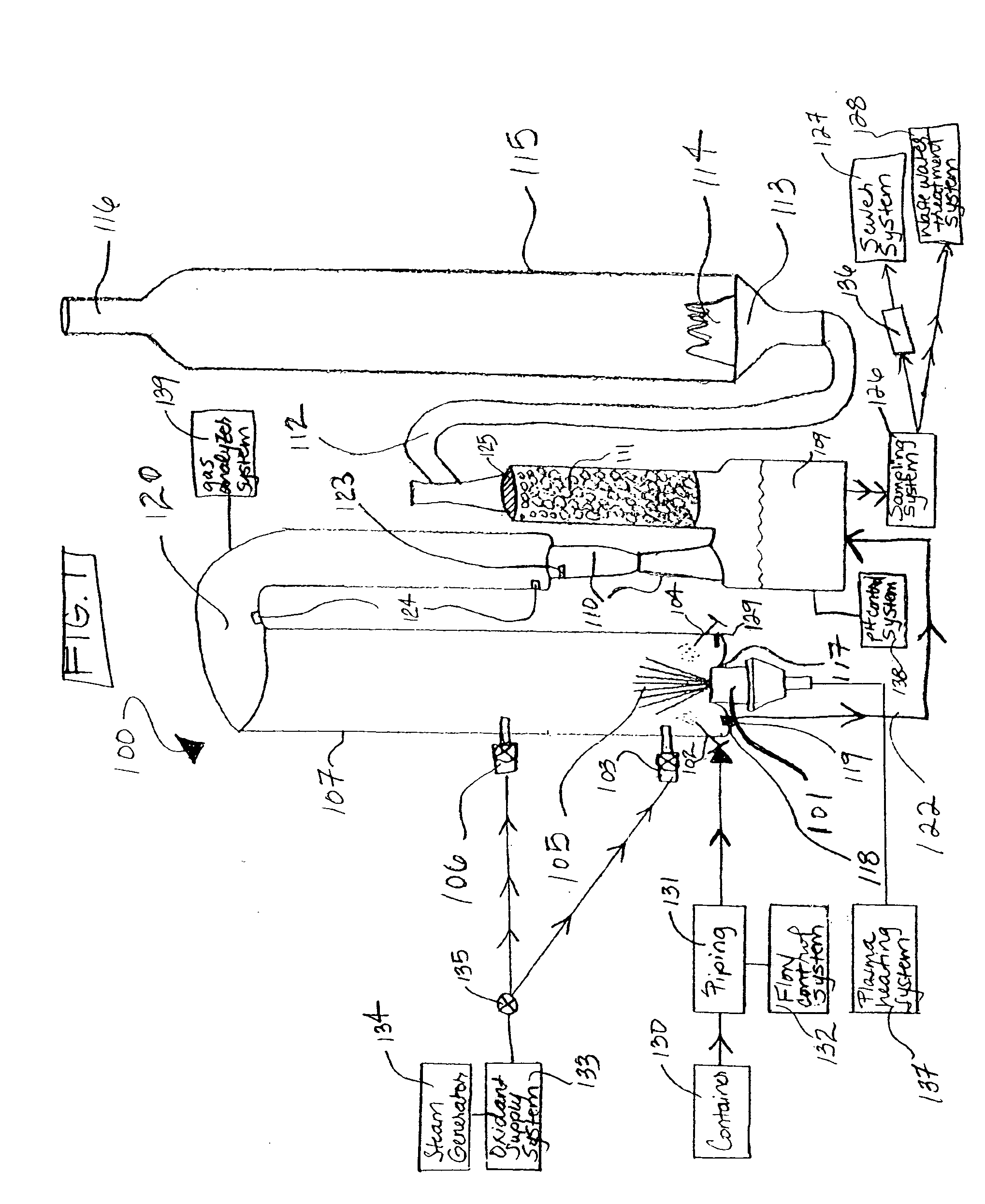
[0009] With reference to the figures, a waste processing system 100 will be described. The waste processing system 100 may be used to treat any type of hazardous and non-hazardous liquid product that may be decomposed upon the application of energy. For example, it may be used to treat liquid materials contaminated with polychlorinated biphenyls (PCBs), industrial and laboratory solvents, organic and inorganic chemicals, pesticides, organo-chlorides, and liquid refinery waste. In addition, the waste processing system 100 may be used to treat solid organic materials that are pulverized or that can be pulverized by a pretreatment system, such as a shredder. The waste product, furthermore, may include organic and inorganic components. Desirably, however, the waste processing system 100 is employed to treat liquid waste including mostly organic materials.

[0010] For ease of reference, the figures and description sometimes refer to the waste as solvent waste, which may include, for examp...


PUM

PropertyMeasurementUnit
temperatureaaaaaaaaaa

Abstract

An apparatus for treating liquid waste includes a vessel, an AC plasma torch mounted with the vessel, and at least one nozzle mounted in the vessel. The nozzle is positioned so that liquid waste introduced through the nozzle into the vessel will be sprayed into or above a flame emitted by the AC plasma torch. Liquid waste is atomized by the nozzle and sprayed into the flame. The energy from the flame causes the organic portion of the atomized liquid waste to gasify and dissociate into elemental components. This dissociation destroys any hazardous or toxic constituency of the waste material.

Description

BACKGROUND [0001] This invention relates to the treatment of waste material, and, more particularly, to the controlled thermal destruction of hazardous and non-hazardous liquid waste materials. [0002] Solvents, such as organic solvents, are commonly used in many industrial applications. The solvent waste created in such applications is often hazardous and contains significant quantities of undesirable halogen compounds, such as organo-chlorides. [0003] Due to the nature of solvent waste, it typically is not recycled for re-use and, instead, is disposed of in a sufficient manner. Incineration has been the principal means by which these materials are treated (landfilling is generally inadequate). In incineration, the hazardous components of the waste are attempted to be destroyed through combustion. [0004] Incineration / combustion, however, has a number of deficiencies. For example, combustion requires large amounts of excess air. It can be difficult and costly to maintain combustion t...

Claims


Application Information

Patent Timeline
Patent Type & Authority Applications(United States)
IPC IPC(8): C01B3/32C10J3/54F23G5/027F23G5/08F23G7/00F23J15/04F23J15/06
CPCF23G7/001C10K3/001F23G2206/203F23G2900/50204F23G2900/54402F23J15/04F23J15/06Y02E20/12Y02E20/363C01B3/32C01B2203/0255C01B2203/0861C01B2203/84C10J3/54C10J3/723C10J2200/152C10J2300/1238C10K1/003C10K1/101C10K1/122F23G5/0276F23G5/085F23G2204/201
Inventor CAPOTE, JOSE AROSIN, JOSEPH A.MENON, FRANK K.
Owner PEAT INT INC
Why Eureka
Try Eureka