Vehicle engine control system utilizing humidity sensor

Active Publication Date: 2005-04-07
FORD GLOBAL TECH LLC
View PDF18 Cites 25 Cited by
  • Summary
  • Abstract
  • Description
  • Claims
  • Application Information

AI Technical Summary

Benefits of technology

[0011] By using the humidity sensor information to both adjust fuel injection and flow through the engine, it is possible to achieve improved overall engine operation. Further, by monitoring sensor operation for degradation, it is possible to utilize default settings in case the humidity sensor degrades. In this way, even as such degradation occurs, measures can be taken to reduce any loss in fuel economy performance and allow operation with minimal engine misfires.
[0012] In this way, overall engine operating performance can be improved.

Problems solved by technology

The inventor of the present application has recognized a disadvantage, however, with prior approaches.
This results in piecemeal systems with no overall structure taking full advantage of humidity sensors for controlling an engine in a vehicle.

Method used


Image

  • Vehicle engine control system utilizing humidity sensor
  • Vehicle engine control system utilizing humidity sensor
  • Vehicle engine control system utilizing humidity sensor

Examples


first embodiment

[0057] A first embodiment to determine whether to enable humidity sensor monitoring is now described with regard to FIG. 8A. Here, the diagnostic is performed upon entering preselected engine operating conditions, such as: at key-on after a long soak (engine off) time. In this embodiment, the second sensor can be a vehicle interior humidity sensor as described in FIG. 1. Note that for a short soak, or for vehicle running operation, the interior sensor may read high due to a sweaty driver or other source of water vapor in the vehicle. Or, it may be low due to the action of an air conditioning system. As such, after a long soak, a more reliable comparison is possible. Even then, however, multiple vehicle trips can be used to increase the reliability of detection. In this way, the monitoring is enabled during selected conditions where both sensors should read similar values, and thus improved detection can be achieved. Note that in an alternative embodiment, one (or both) humidity sign...

second embodiment

[0060] A second embodiment performs the diagnostic on a continuous basis. This can be used when such continuous monitoring may be needed to determine degradation throughout vehicle operation. In this case the interior humidity sensor may not be used. Rather, the second humidity sensor is installed in the vehicle in a location where it would read close to the same air stream as the first sensor, whether it is in the engine inlet airflow stream or the ambient stream. Again, the electrical circuits can be designed to minimize the potential of common degradation of the sensors simultaneously. Also, the routine of FIG. 8B can perform the reading of the sensors for diagnosis when they have reached an equilibrium value by using filters, for example.

[0061] Referring now specifically to FIG. 8B, in step 830, the routine determines whether the time since vehicle key on is greater than a threshold values (TIME_ON_VALUE). If so, in step 840, diagnosis is enabled. Thus, by using the key on time ...


PUM


Abstract

A system and method for utilizing a humidity sensor with an internal combustion engine of a vehicle is described. Specifically, information from the humidity sensor is used to adjust a desired air-fuel ratio to reduce engine misfire while improving vehicle fuel economy. Further, such information is also used to adjust timing and / or lift of the valve in the engine cylinder. Finally, diagnostic routines are also described.

Description

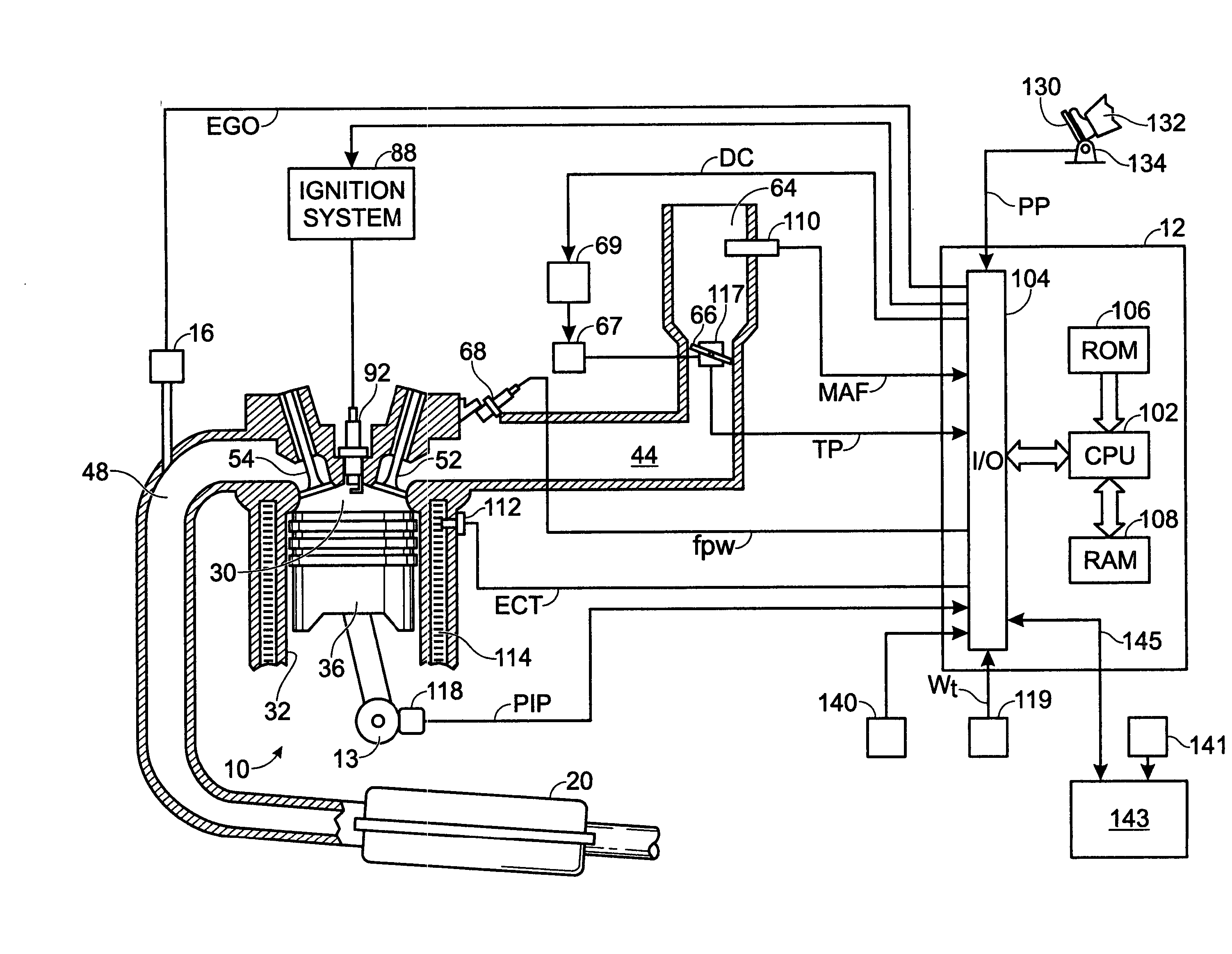
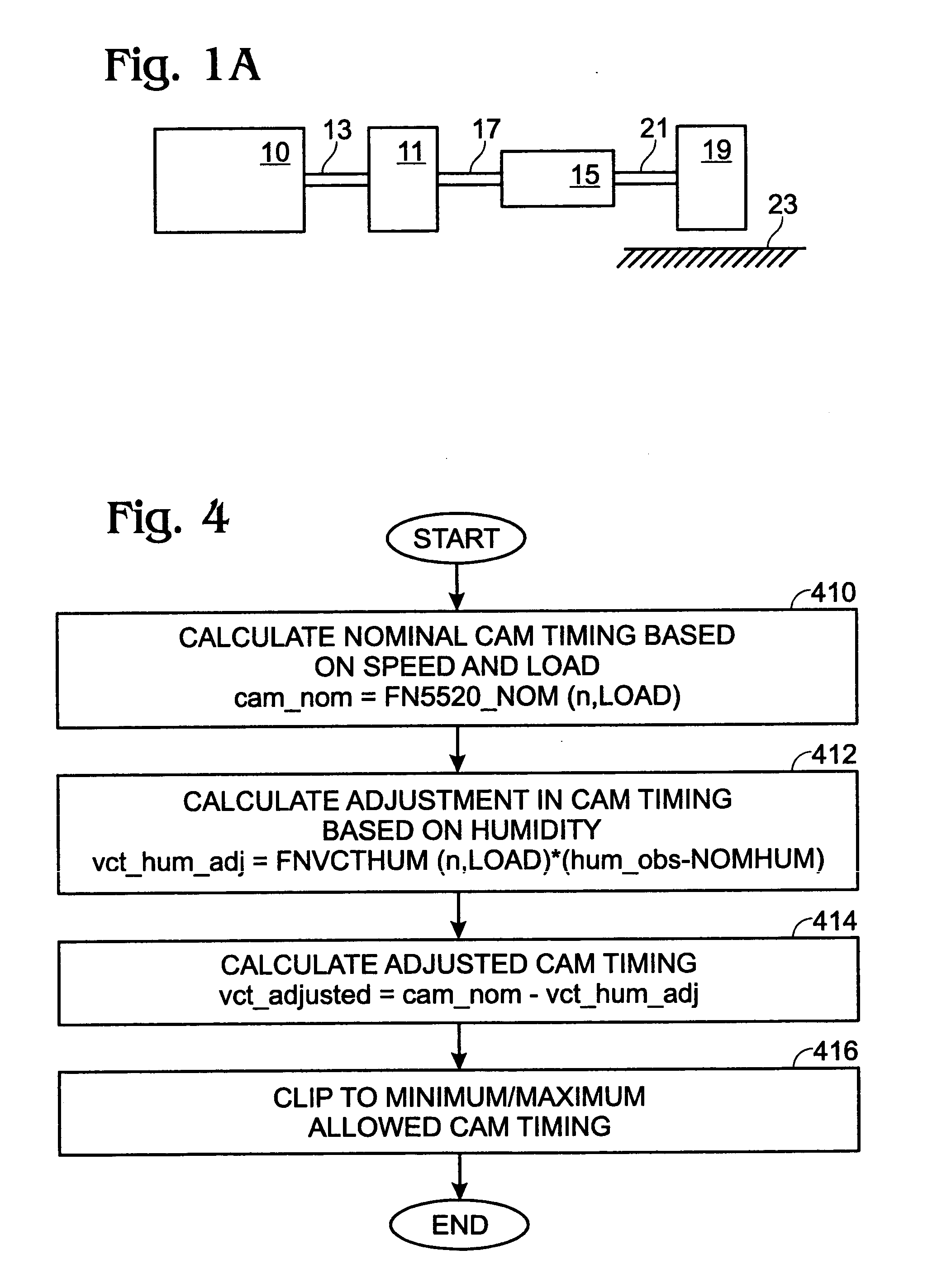
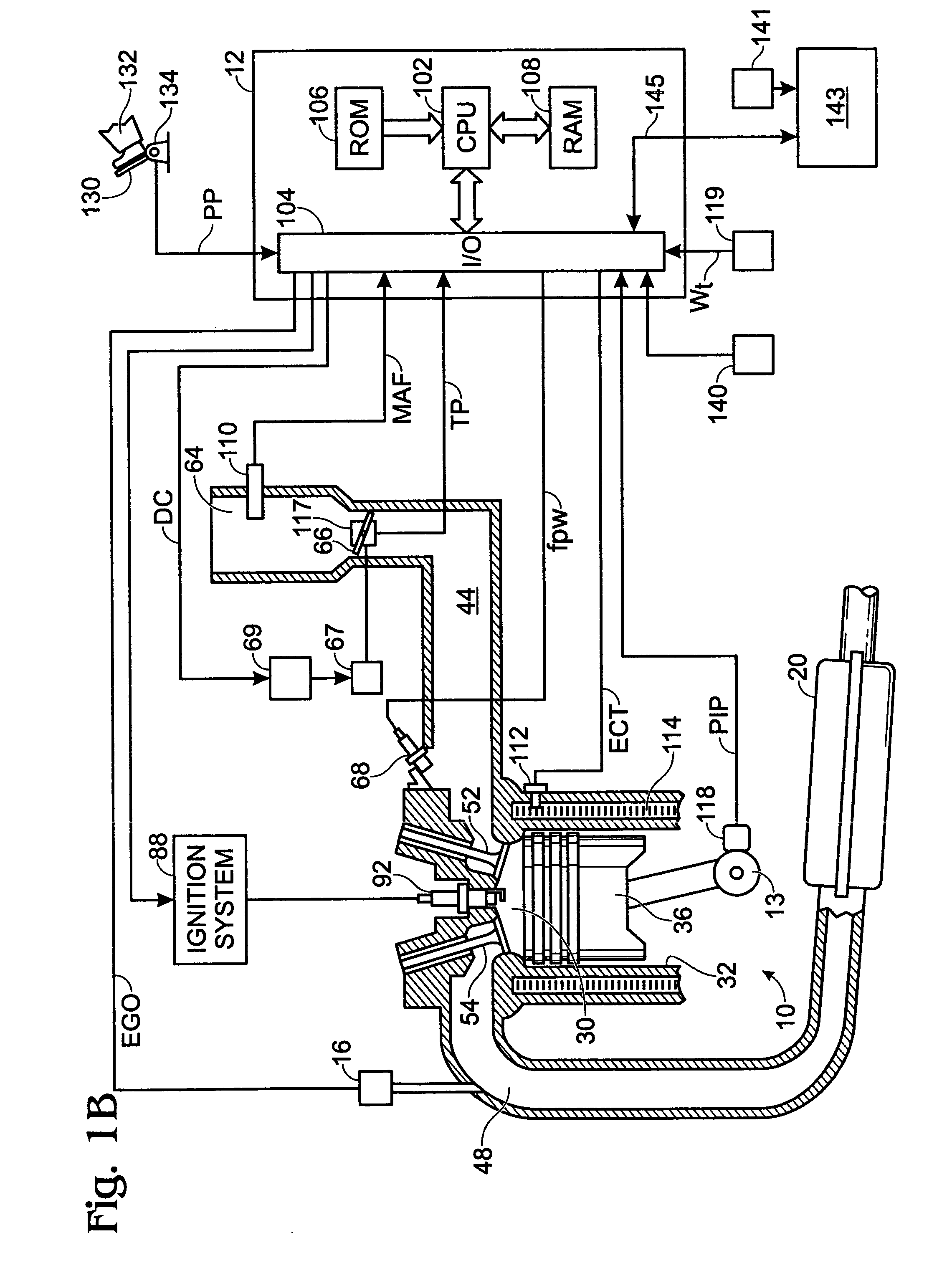
FIELD OF THE INVENTION [0001] The field of the present invention relates generally to the control of engine operation to reduce engine misfire conditions while maximizing engine fuel economy for passenger vehicles driven on the road. BACKGROUND OF THE INVENTION [0002] Various references describe specific uses for a humidity sensor in controlling an engine in certain specific conditions. See for example, U.S. Pat. No. 6,062,204. [0003] The inventor of the present application has recognized a disadvantage, however, with prior approaches. In particular, prior art approaches have tended to focus on a specific, or narrow, application in which a humidity sensor is utilized. This results in piecemeal systems with no overall structure taking full advantage of humidity sensors for controlling an engine in a vehicle. SUMMARY OF THE INVENTION [0004] Therefore, the inventors herein have developed a system taking advantage of a humidity sensor for engine control in a vehicle. [0005] In one examp...

Claims


Application Information

Patent Timeline
IPC IPC(8): F02D41/00F02D41/14F02D41/18F02D41/22
CPCF02D41/006F02D41/0065F02D41/1475Y02T10/40F02D41/222F02D2041/001F02D2200/0418F02D41/18
Inventor CULLEN, MICHAEL J.
Owner FORD GLOBAL TECH LLC
Why Eureka
Try Eureka