Membrane devices with controlled transmembrane pressure and method of use

a membrane device and transmembrane technology, applied in the direction of membranes, filtration separation, separation processes, etc., can solve the problems of pressure drop from the feed end of the module to the retentate end, and achieve the effect of constant tmp, increased resistance in the permeable cavity, and controllable and essentially constant tmp

Active Publication Date: 2005-04-07
SEPARIS
View PDF11 Cites 16 Cited by
  • Summary
  • Abstract
  • Description
  • Claims
  • Application Information

AI Technical Summary

Benefits of technology

[0003] One means of equalizing the TMP from a feed end of a membrane module to the retentate end is to circulate permeate in co-current flow along the exterior of a membrane element or elements contained in a permeate collection housing. The pressure drop for the flowing permeate can be controlled to match the feed to retentate pressure drop, thereby resulting in a controllable and essentially constant TMP along the length of the membrane elements. This means was disclosed in 1978 by Sandblom, in U.S. Pat. No. 4,105,547, assigned to Alfa-Lav

Problems solved by technology

This high crossflow velocity also results in a pressure d

Method used


Image

  • Membrane devices with controlled transmembrane pressure and method of use
  • Membrane devices with controlled transmembrane pressure and method of use
  • Membrane devices with controlled transmembrane pressure and method of use

Examples


Embodiment Construction

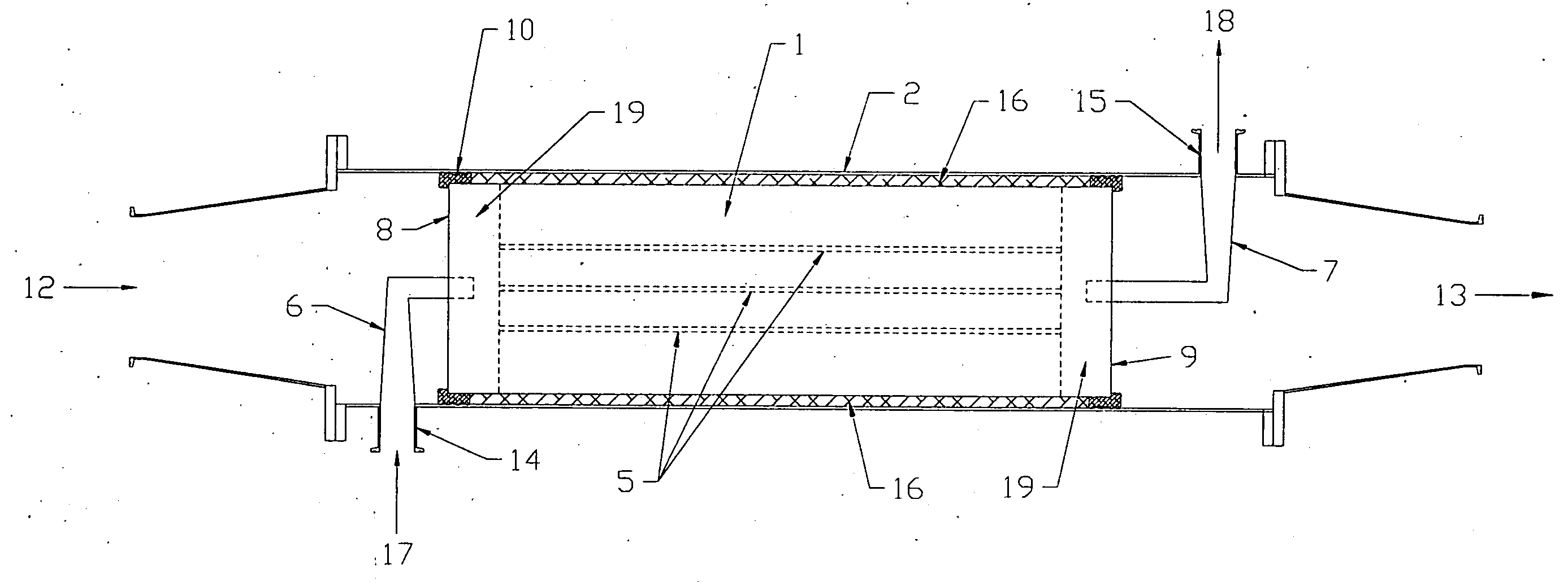
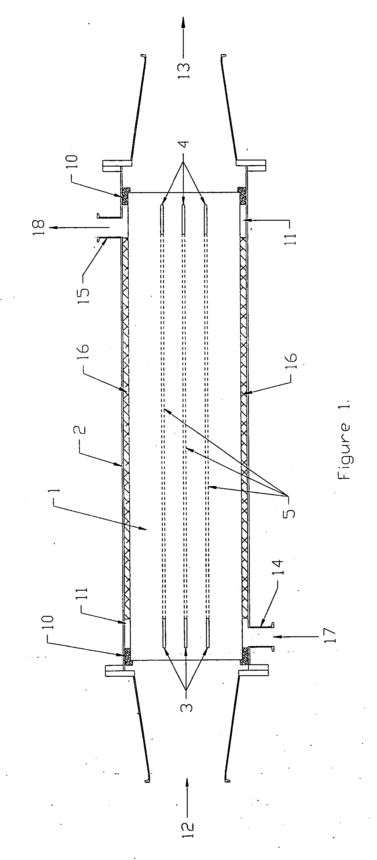
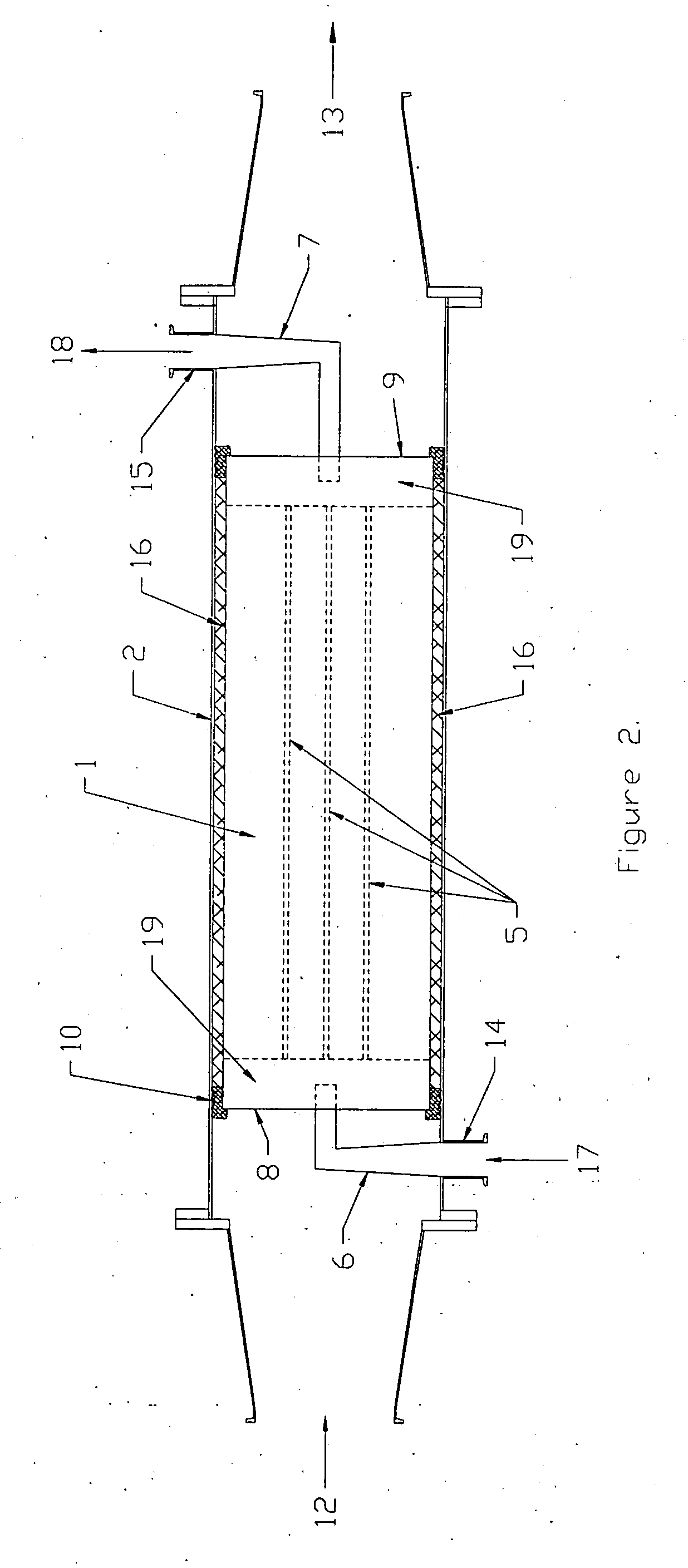
[0027] In FIG. 1, a monolith membrane element 1 is contained with a module housing 2, with means 10 for isolating a permeate collection zone 11 from a feedstock inlet 12 and a retentate outlet 13. The membrane element contains one or more transverse slots 3 and 4 at the feed inlet and retentate outlet ends of the element, respectively, or other channels. The slots transect a plurality of longitudinal permeate conduit chambers 5, and this constitutes one form of a permeate conduit, as described in the above-referenced Goldsmith patents. Permeate ports 14 and 15 are located on the module housing near the inlet and outlet ends, respectively. A flow resistance material 16 can be used to fill the permeate collection zone annulus situated between the membrane element and the module housing to increase the permeate flow resistance in this annular space.

[0028] In operation, depending on crossflow velocity, feed viscosity, membrane element channel diameter and channel length, an operating p...


PUM

PropertyMeasurementUnit
Pore sizeaaaaaaaaaa
Pore sizeaaaaaaaaaa
Lengthaaaaaaaaaa

Abstract

A crossflow membrane device that receives a feedstock at a feed end face and separates the feedstock into permeate and retentate. The device has a membrane support containing at least one monolith of porous material defining a plurality of passageways extending longitudinally from the feed end face of the monolith to a retentate end face of the monolith through which the feedstock flows to pass retentate from the device. A permselective membrane coating of finer pore size than that of the porous material is applied to the passageway wall surfaces of the monolith. At least one permeate conduit is formed within the monolith, the conduit containing a plurality of longitudinal permeate chambers communicating with a means of permeate introduction at or near the feed end face and permeate withdrawal at or near the retentate end face. The permeate is separated from feed and retentate, and a portion of the permeate is circulated through the permeate conduit to create a decreasing permeate pressure within the permeate conduit from the feed end of the membrane device to the retentate end of the device to control transmembrane pressure along the length of the device.

Description

FIELD OF THE INVENTION [0001] This invention relates to an improved crossflow membrane device that receives a feedstock at a feed end face and separates the feedstock into permeate and retentate. The device has a membrane support containing at least one monolith of porous material defining a plurality of passageways extending longitudinally from the feed end face of the monolith to a retentate end face of the monolith. At least one permeate conduit is formed within the monolith, the conduit containing a plurality of longitudinal permeate chambers communicating with a means of permeate introduction at or near the feed end face and permeate withdrawal at or near the retentate end face. The permeate is separated from feed and retentate, and a portion of the permeate is circulated through the permeate conduit co-currently with feedstock flow to control transmembrane pressure along the length of the device. BACKGROUND OF THE INVENTION [0002] For crossflow microfiltration and ultrafiltrat...

Claims


Application Information

Patent Timeline
IPC IPC(8): B01DB01D61/00B01D61/14B01D63/00B01D63/06B01D65/08
CPCB01D61/145B01D61/147B01D63/066B01D65/08B01D2311/06B01D2311/13B01D2321/2016B01D2311/14B01D2313/12B01D2313/146
Inventor GOLDSMITH, ROBERT L.BISHOP, BRUCE A.
Owner SEPARIS
Why Eureka
Try Eureka