Load driving circuit with current detection capability
a technology of current detection and driving circuit, which is applied in the direction of motor/generator/converter stopper, dynamo-electric converter control, instruments, etc., can solve the problems of low detection resistor, difficult voltage detection, and loss of power supply voltage vsub>m, so as to reduce power consumption and reduce power consumption. , the effect of low cos
- Summary
- Abstract
- Description
- Claims
- Application Information
AI Technical Summary
Benefits of technology
Problems solved by technology
Method used
Image
Examples
first embodiment
1. FIRST EMBODIMENT OF THE PRESENT INVENTION
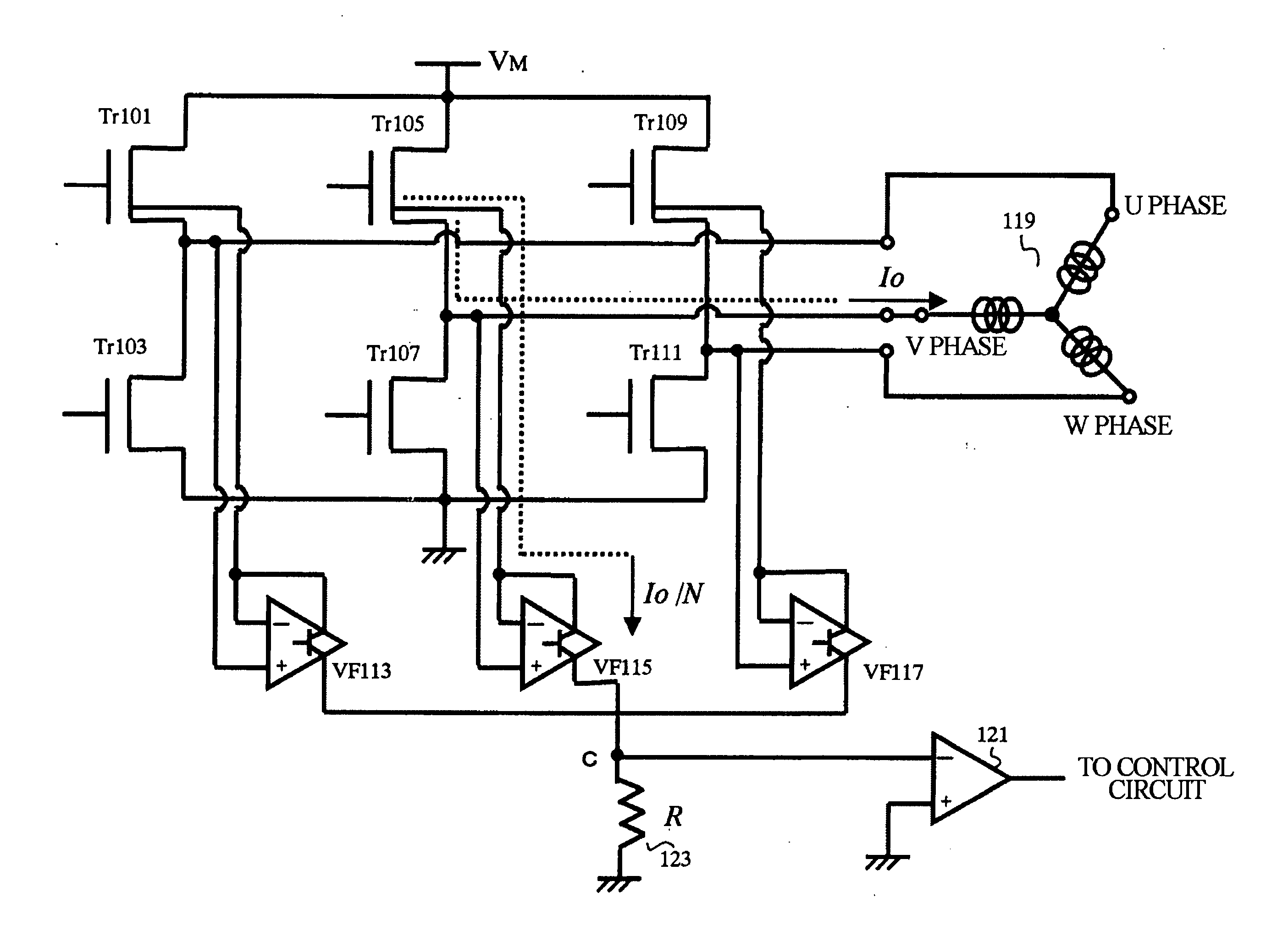
[0030] 1-(1) Description of a Load Driving Circuit
[0031] In this embodiment, transistors Tr (hereinafter, referred to as Tr) 101-111 are implemented by n-channel MOS transistors.
[0032] A description will be given of a load driving circuit according to the first embodiment of the present invention by referring to FIG. 1. The control circuit (not shown) drives a motor 119 by subjecting Tr 101-111 to on and off switching and by supplying, according to a predetermined pattern, a driving current Io to U-phase through W-phase current driving terminals constituting the motor 119.
[0033] Tr 101, Tr 105 and Tr 109 are connected with a motor power supply VM and arranged in parallel with each other, the drains of Tr being connected to the motor power supply VM and the gates thereof being connected to a control circuit (not shown). The sources of Tr are divided into output sources (S1) and detection sources (S2). A detailed description thereof will ...
second embodiment
2. SECOND EMBODIMENT OF THE PRESENT INVENTION
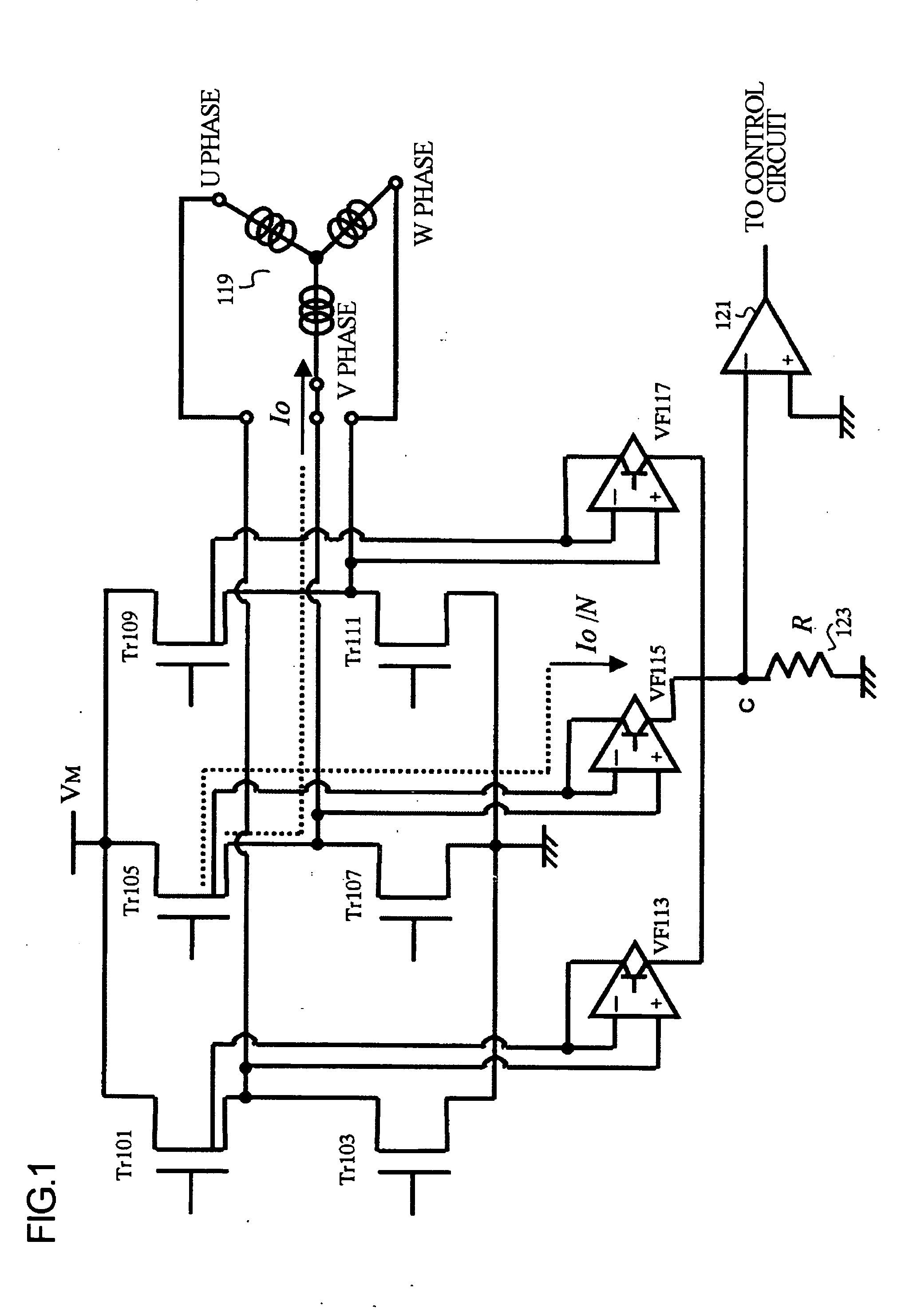
[0059] 2-(1) Description of a Load Driving Circuit
[0060] In this embodiment, transistors Tr (hereinafter, referred to as Tr) 101, 105 and 109 are implemented by p-channel MOS transistors, and Tr 103, 107 and 111 are implemented by n-channel MOS transistors.
[0061] A description will be given of a load driving circuit according to the second embodiment of the present invention by referring to FIG. 1. The control circuit (not shown) drives the motor 119 by subjecting Tr 101-111 to on and off switching and by supplying, according to a predetermined pattern, the driving current Io to U-phase through W-phase current driving terminals constituting the motor 119.
[0062] Tr 101, Tr 105 and Tr 109 are connected with the motor power supply VM and arranged in parallel with each other, the sources of Tr being connected to the motor power supply VM and the gates thereof being connected to the control circuit (not shown). The drains of Tr are divided ...
third embodiment
3. THIRD EMBODIMENT OF THE PRESENT INVENTION
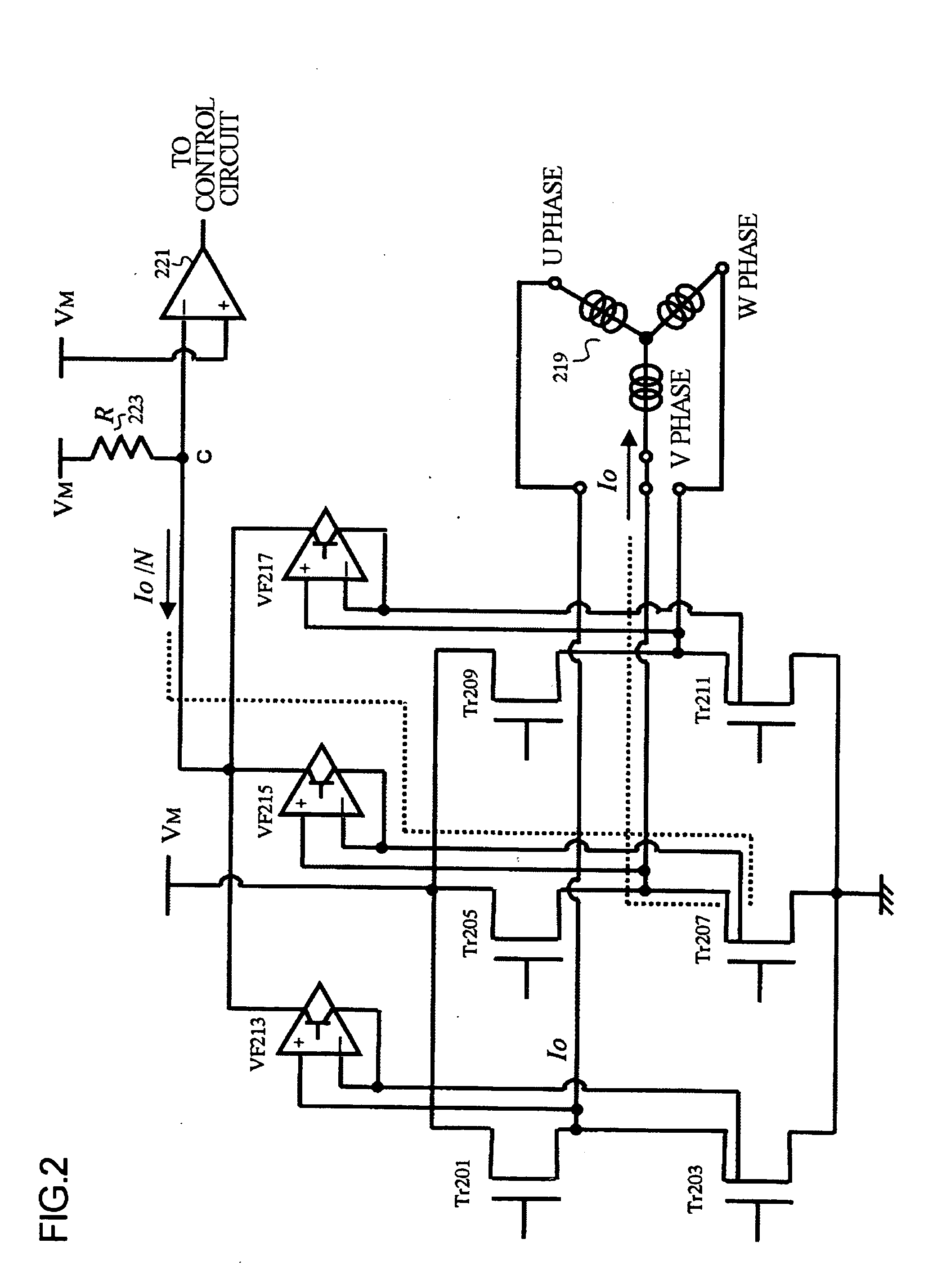
[0088] 3-(1) Description of a Load Driving Circuit
[0089] In this embodiment, transistors Tr (hereinafter, referred to as Tr) 201-211 are implemented by n-channel MOS transistors.
[0090] A description will be given of a load driving circuit according to the third embodiment of the present invention by referring to FIG. 2. The control circuit (not shown) drives the motor 219 by subjecting Tr 201-211 to on and off switching and by supplying, according to a predetermined pattern, the driving current Io to U-phase through W-phase current driving terminals constituting the motor 219.
[0091] Tr 201, Tr 205 and Tr 209 are connected with a motor power supply VM and arranged in parallel with each other, the drains of Tr being connected to the motor power supply VM and the gates thereof being connected to a control circuit (not shown). The source of Tr 201 is connected to the output drain (D1) of Tr 203. The source of Tr 205 is connected to the outp...
PUM
 Abstract
Description
Claims
Application Information
 - R&D
- Intellectual Property
- Life Sciences
- Materials
- Tech Scout
- Unparalleled Data Quality
- Higher Quality Content
- 60% Fewer Hallucinations
Browse by: Latest US Patents, China's latest patents, Technical Efficacy Thesaurus, Application Domain, Technology Topic, Popular Technical Reports.
© 2025 PatSnap. All rights reserved.Legal|Privacy policy|Modern Slavery Act Transparency Statement|Sitemap|About US| Contact US: help@patsnap.com


