
Portable image receiving device

a technology for receiving devices and portable terminals, which is applied in the direction of power management, television systems, high-level techniques, etc., can solve the problem that the control unit cannot allow the audio output to a loudspeaker, and achieve the effect of extending the allowable time of their use and reducing the consumed curren

Active Publication Date: 2005-04-07
LENOVO INNOVATIONS LTD HONG KONG
View PDF12 Cites 14 Cited by
  • Summary
  • Abstract
  • Description
  • Claims
  • Application Information

AI Technical Summary

Benefits of technology

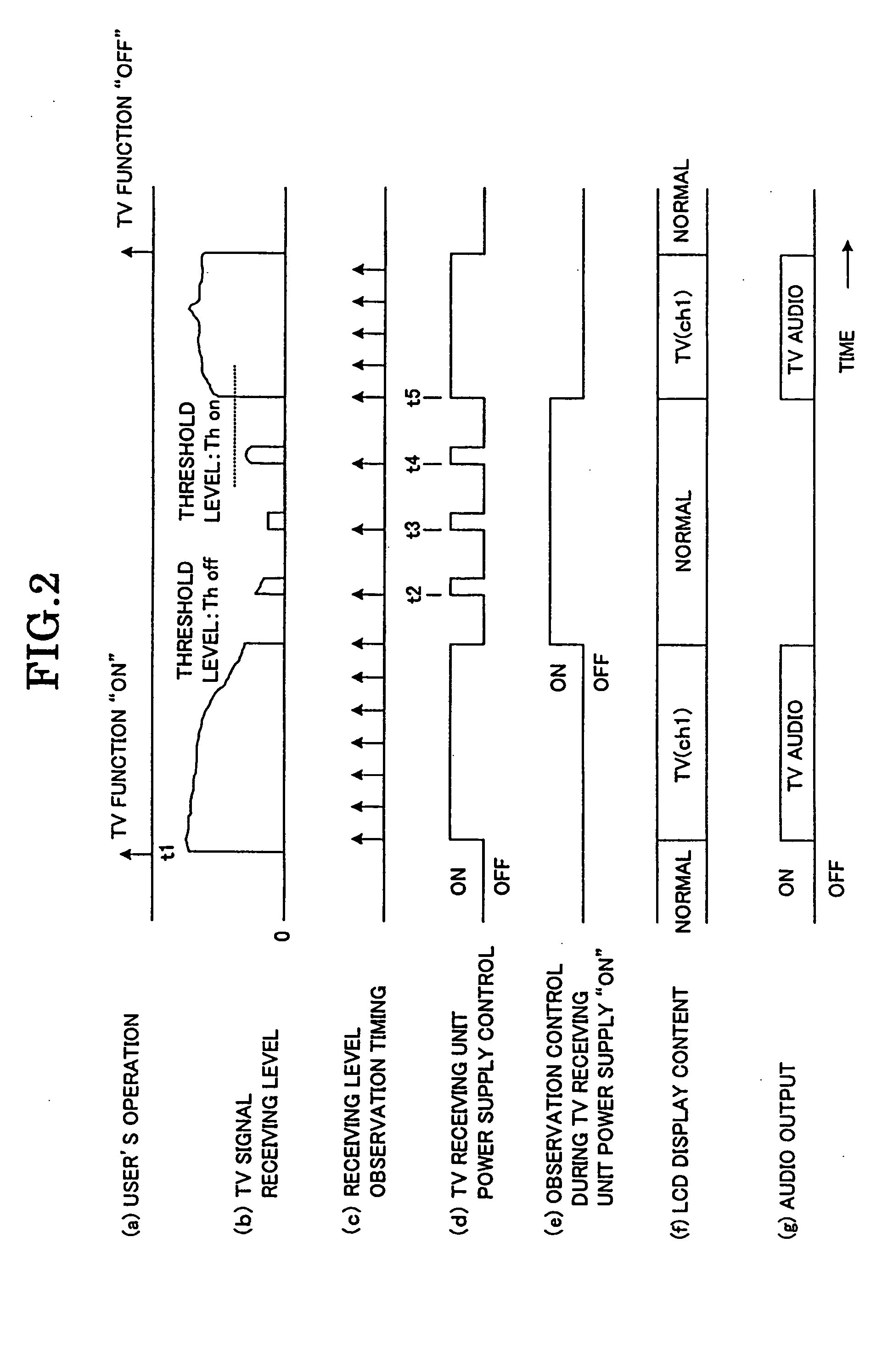
The present invention provides a portable receiving device and portable terminal device that can control the power supply based on the TV radio wave receiving status to reduce the consumed current and extend the allowable time of their use. The device detects the TV signal receiving level and turns off the power supply when the receiving level becomes lower than a preset threshold level. The device can also detect the receiving level intermittently and resume the power supply when the receiving level exceeds the threshold level. This allows the device to reduce power consumption and extend the time of TV reception enjoyment.

Problems solved by technology

The control unit does not allow the audio output to a loudspeaker or the like and the video output to the display unit.

Method used


Image

  • Portable image receiving device
  • Portable image receiving device
  • Portable image receiving device

Examples


first embodiment

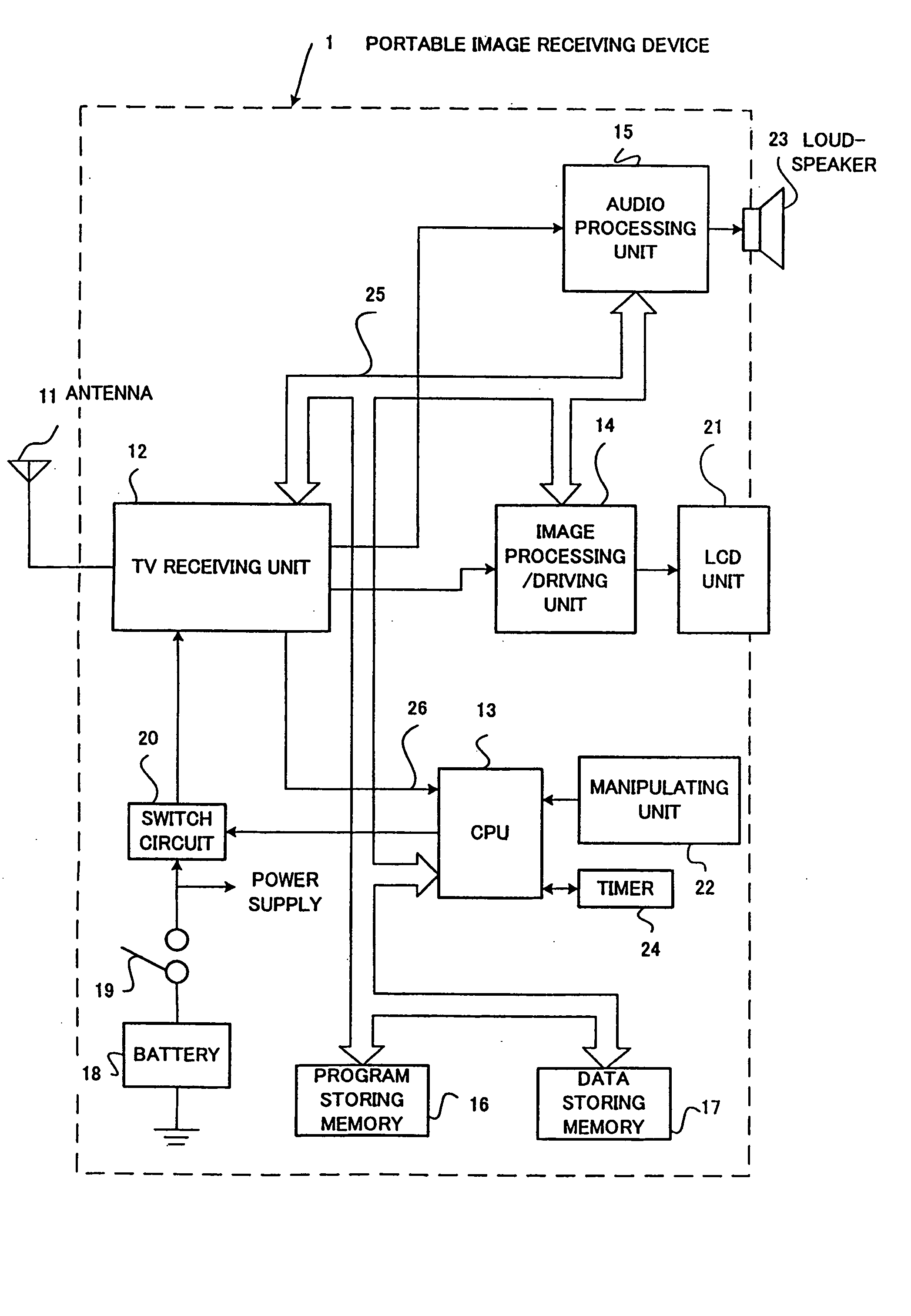
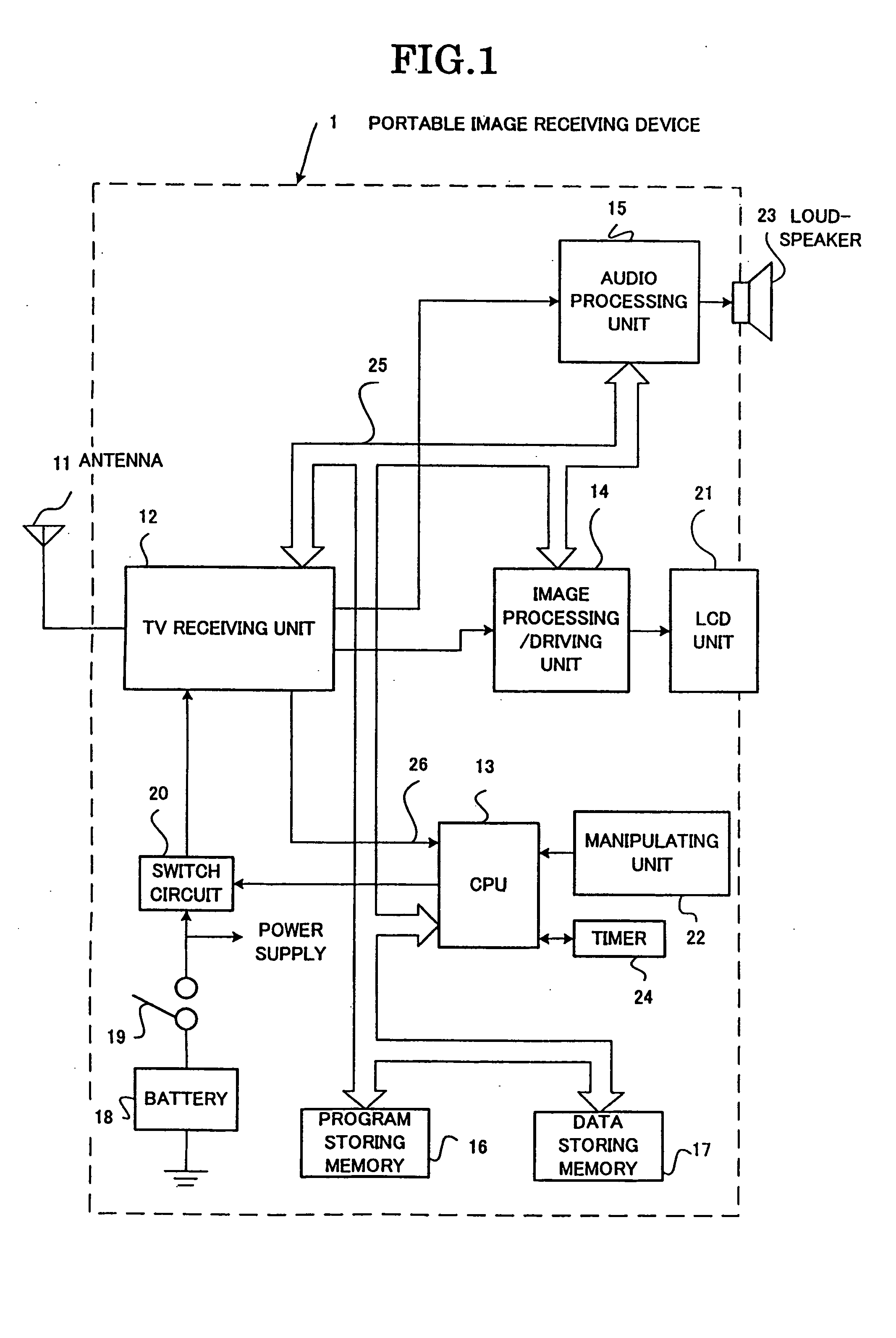
[0033]FIG. 1 shows the portable image receiving device according to the present invention. The portable image receiving device 1 comprises an antenna 11, a TV receiving unit 12 (abbreviated as receiving unit), a CPU 13, an image processing / driving unit 14, an audio processing unit 15, a program storing memory 16, a data storing memory (or memory unit) 17, a battery 18 as power supply, a power supply switch 19, a switch circuit 20, an LCD (liquid crystal display) unit 21, a manipulating unit 22, a loudspeaker 23 and a timer 24. Reference numeral 25 designates a bus inter-connecting the CPU 13 and other circuits for digital processing. The CPU 13 and the switch circuit 20 together constitute a control unit.

[0034] The antenna 11 has a property of covering a frequency band, by which all the television broadcast channel frequencies can be received, and it may, for instance, be an extensible rod antenna. It is possible to connect or provide an external connection antenna to permit high se...

second embodiment

[0049]FIG. 3 shows the arrangement of the present invention applied to a portable terminal device. Here a portable telephone set with TV function will be described as portable terminal device. The portable terminal device 30 shown in FIG. 3 comprises a portable telephone unit, a TV function unit and a battery 49 as power supply.

[0050] The portable telephone set includes an antenna 31 for portable telephone unit, a radio unit 32, a baseband unit 33, a voice CODE / control unit 34, a microphone 35 as transmitter, a receiver (or loudspeaker) 36, a display data control unit 37, an LCD display unit 38, a CPU 39, a key matrix input unit 40 as a manipulating unit, a timer 41, a program storing memory 42 and a data storing memory (or memory unit) 43. Reference 44 designates a bus, which interconnects the CPU 39 and other circuits for executing digital processing and it includes an address bus, a data bus and a control bus. The TV function unit is constituted by a TV antenna 45, a TV receiving...


PUM


Abstract

In a portable receiving device 1 operable with a battery 18 as power supply and capable of receiving the TV broadcast outdoors, a CPU 13 detects the receiving level of the TV receiving unit 12 at timings set in the timer 24, compares the receiving level with a preset threshold level, turns off, when the receiving level becomes lower than a threshold level, the power supply to the TV receiving unit 12, subsequently detecting and performs, when the receiving level subsequently exceeds a threshold level, a control for resuming the power supply to the receiving unit 12. Thus, the power consumption in the TV receiving unit 12 when the TV radio wave receiving status is deteriorated is reduced.

Description

BACKGROUND OF THE INVENTION [0001] This application claims benefit of Japanese Patent Application No. 2003-272858 filed on Jul. 10, 2003, the contents of which are incorporated by the reference. [0002] The present invention relates to portable image receiving devices and portable terminal devices such as portable image receiving devices capable of extending the allowable time (life time) of use of a power supply battery. [0003] In our current daily life, the telephone set and the television (TV) receiver have become essential electronic devices, and their various portable models have been developed with advancement of semiconductor techniques and realization of color and improved performance liquid crystal displays (LCD). For example, portable image receiving devices permitting outdoor TV broadcast reception have been reduced in size and weight down to a size capable of being put on a palm with realization of image display on a display unit (such as LCD) of several inches. [0004] Th...

Claims


Application Information

Patent Timeline
Patent Type & Authority Applications(United States)
IPC IPC(8): H04B1/16H04B7/26H04B17/30H04M1/00H04M1/73H04N5/44H04N5/63H04W52/02H04W88/02
CPCH04B1/1615H04N5/63H04N21/41407H04N21/44209Y02B60/50H04N21/6112H04N21/6181H04W52/0245H04N21/4432Y02D30/70
Inventor TAKAHASHI, NAOMICHI
Owner LENOVO INNOVATIONS LTD HONG KONG
Learn More