Supercharge Your Innovation With Domain-Expert AI Agents!

High optical rejection optical spectrum analyzer/monochromator

a spectrum analyzer and optical spectrum technology, applied in the field of optical spectrum analyzers and monochromators, can solve the problems of noise floor, important limitations of optical rejection ratio (orr), and limitations, and achieve the effect of narrow spectral linewidth response and high optical rejection ratio

Active Publication Date: 2005-04-07
EXFO ELECTRO OPTICAL ENG
View PDF27 Cites 11 Cited by
  • Summary
  • Abstract
  • Description
  • Claims
  • Application Information

AI Technical Summary

Benefits of technology

The present invention seeks to substantially avoid at least some of the afore-mentioned disadvantages and to provide a compact optical design of optical spectrum analyzer / monochromator advantageously having both a narrow spectral linewidth response and extremely high optical rejection ratio, especially near the peak.
The collimating / focussing optical means of the second stage preferably has a longer focal length than that of the first stage, so as to reduce the angle from the optical axis resulting from the limited physical proximity of the four ports arranged on a rectangle, thus reducing aberrations and coupling losses by ensuring that the angle between the optical axis and the beams is kept small. This also keeps the spot sizes of the two beams small which allows a narrow line width response to be achieved.

Problems solved by technology

Both their designs have advantages and weaknesses that are complementary, but they both suffer from important limitations with regard to the optical rejection ratio (ORR) and, at different levels, the noise floor.
In the case of the He et al's OSA described in U.S. 20010030745, these limitations arise from the fact that the light is filtered only once, even after two passes on the grating.
Although this leads to a reduced spectral linewidth response, the resulting optical spectrum analyzer still has a limited level optical noise floor and its optical rejection ratio (ORR) is not improved; it is, in fact, degraded by the extra loss incurred while the noise floor remains unchanged.
This approach has the advantage of very high ORR filter response close to the peak, but the ultimate noise floor is limited by back-reflection from the common input and output lens, a limitation that becomes important when multiple signal wavelengths are to be analyzed, as is the case in DWDM systems that, in practice, require the high ORR.
Other limitations include the use of large expensive components, the size / cost of the polarization beam splitter (120) within the monochromator section limiting the ultimately achievable filter response linewidth and the need for the components to be precisely polished to ensure that the optical beams of both polarizations can be recombined at the output of the monochromator.
While it might be possible to improve the spectral linewidth response for both these approaches by increasing the component dimensions (namely the lenses' focal lengths and the diffraction grating surface and, for Lefevre et al., the polarizing beam splitter), it would be at the expense of a larger occupied volume, higher cost and greater mounting difficulty.

Method used


Image

  • High optical rejection optical spectrum analyzer/monochromator
  • High optical rejection optical spectrum analyzer/monochromator
  • High optical rejection optical spectrum analyzer/monochromator

Examples


second embodiment

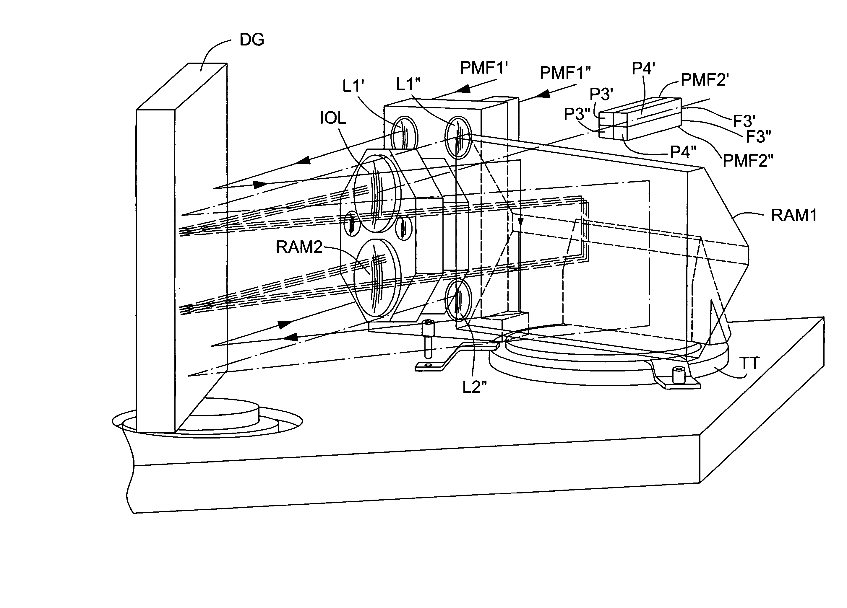
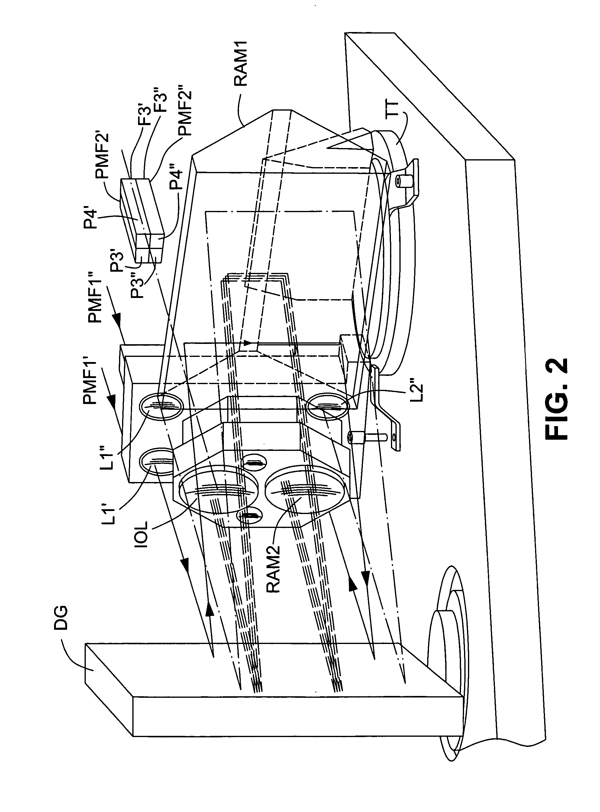
the invention, embodying some of these modifications, will now be described with reference to FIG. 9 in which components corresponding to those in FIGS. 1 to 5 have the same reference designation. Basically, retroreflector RAM2 has been omitted and lens IOL replaced by lenses L3 and L4. Also, the lenses L3 and L4 are further apart, as compared with the configuration of the optical block shown in FIG. 5 for the OSA of FIG. 1, and the lenses L1′, L1″, L2′, L2″ are between them.

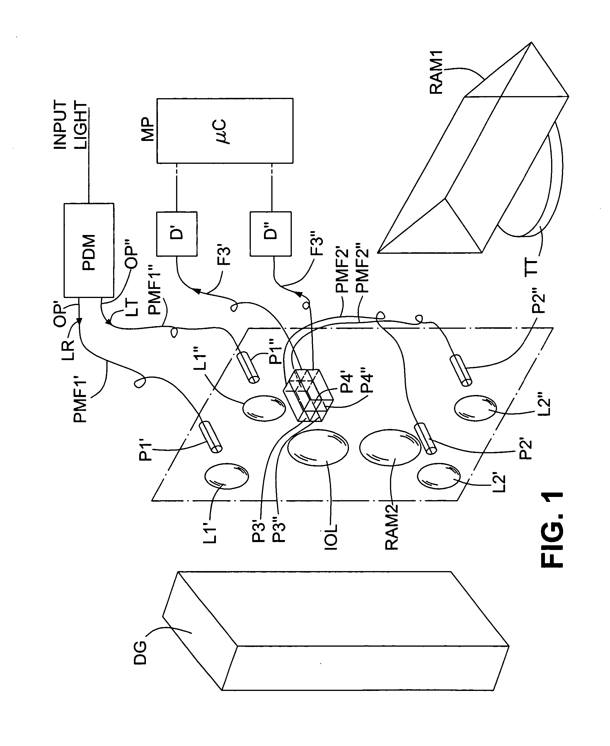
Referring to FIG. 9, the polarization decomposition means PDM, as before, splits an input light beam into its first and second components having mutually-orthogonal linear SOPs and outputs them via polarization-maintaining fibers PMF1′ and PMF1″, respectively, to first and second input ports P1′ and P1″, respectively, so that, when the first and second light beams LR and LT are launched into the monochromator first stage via ports P1′ and P1″, respectively, their linear SOPs are parallel to each other and to th...


PUM


Abstract

A dual-channel, double-filtering, multi-pass OSA having a narrow spectral linewidth response and high ORR comprises a diffraction grating (DG), two input ports (P1′, P1″) for directing first and second input light beams (LR, LT) onto the grating; a retroreflector (RAM1) for returning the dispersed light beams to the grating for dispersion again; two intermediate output ports (P2′, P2″) for receiving the twice-dispersed light beams; two secondary input ports (P3′, P3″) coupled to the intermediate output ports by polarization-maintaining waveguides (PMF2′, PMF2″) for directing the light beams onto the grating a third time, with their SOPs having a predetermined orientation relative to the SOPs of the first and second light beams when first incident upon the grating, the retroreflector (RAM1) returning the three-times-dispersed light beams to the grating for dispersion a fourth time; and two output ports (P4′, P4″) for receiving the light beams after dispersion the fourth time.

Description

TECHNICAL FIELD This invention relates to optical spectrum analyzers and monochromators of the kind which use a diffraction grating. The invention is especially applicable to optical spectrum analyzers, and to monochromators for use therein, in which a light beam to be analyzed is applied to the diffraction grating more than once so as to obtain improved resolution. BACKGROUND ART The invention is concerned especially with high performance diffraction grating-based optical spectrum analyzers (OSA) and monochromators. U.S. Pat. No. 5,233,405 (Wildnauer et al.), for example, discloses a double-pass, double-filtering monochromator using a Littrow configuration that has a waveplate positioned in the middle of the monochromator so that the light impinges upon the grating a second time with a polarization state orthogonal to the state of polarization when it impinged upon it the first time to reduce the PDL in combination with using a Littrow configuration with a grating having a small ...

Claims


Application Information

Patent Timeline
IPC IPC(8): G01J3/18
CPCG01J3/02G01J3/0202G01J3/021G01J2003/1819G01J3/0294G01J3/18G01J3/0224
Inventor HE, GANGGARIEPY, DANIEL
Owner EXFO ELECTRO OPTICAL ENG
Features
  • R&D
  • Intellectual Property
  • Life Sciences
  • Materials
  • Tech Scout
  • Unparalleled Data Quality
  • Higher Quality Content
  • 60% Fewer Hallucinations
Learn More