Solid state multi-pole switching device for plug-in switching units

a multi-pole switching and plug-in technology, applied in the direction of programmable/customizable/modifiable circuits, non-printed jumper connection addition, emergency protective arrangements for limiting excess voltage/current, etc., can solve the problems of affecting the operation of the switch, and unable to readily switch multiple circuits grouped together in selected groups, etc., to achieve the effect of easy installation and programing

Inactive Publication Date: 2005-04-07
TANIS JAMES
View PDF6 Cites 49 Cited by
  • Summary
  • Abstract
  • Description
  • Claims
  • Application Information

AI Technical Summary

Benefits of technology

[0011] The solid state multi-pole switching device of the present invention allows an installer or user to program the desired input / output switching connections in the field or for onsite operation. The output circuits can be grouped and controlled by input control signals in any desired combination. The device can therefore be used in a wide range of multi-circuit switching control applications such as commercial, industrial or home lighting, including but not limited to store lighting and display, stadium lighting, office space lighting, industrial plant lighting or school lighting. It is made modular so that only the necessary input control modules and output switch units need to be installed at any time. The modular components can be individually replaced without replacing the entire unit, or disturbing other circuits. After initial installation, more control modules and / or plug-in switch units can be easily installed and programmed as desired.

Problems solved by technology

Switching devices that employ a mechanical contact to switch power on / off to a circuit are subject to mechanical failure, wear, corrosion, current transients, and other problems that can degrade their performance.
However, this prior type of solid-state switching device is used to switch connected or dedicated circuits, and cannot readily be used to switch multiple circuits grouped together in selected groups and controlled by selectable input control signals.

Method used


Image

  • Solid state multi-pole switching device for plug-in switching units
  • Solid state multi-pole switching device for plug-in switching units
  • Solid state multi-pole switching device for plug-in switching units

Examples


Embodiment Construction

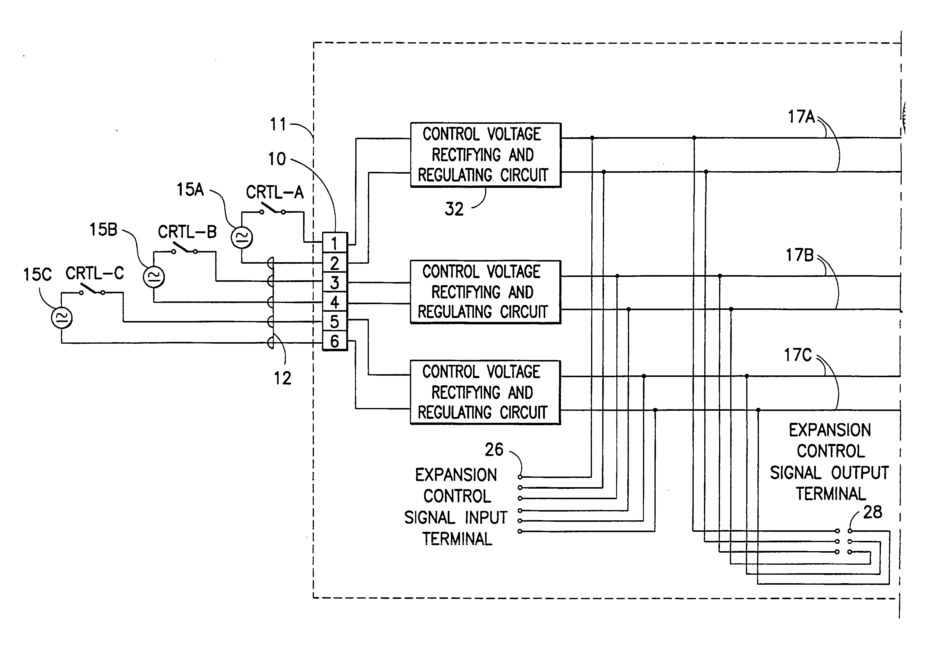
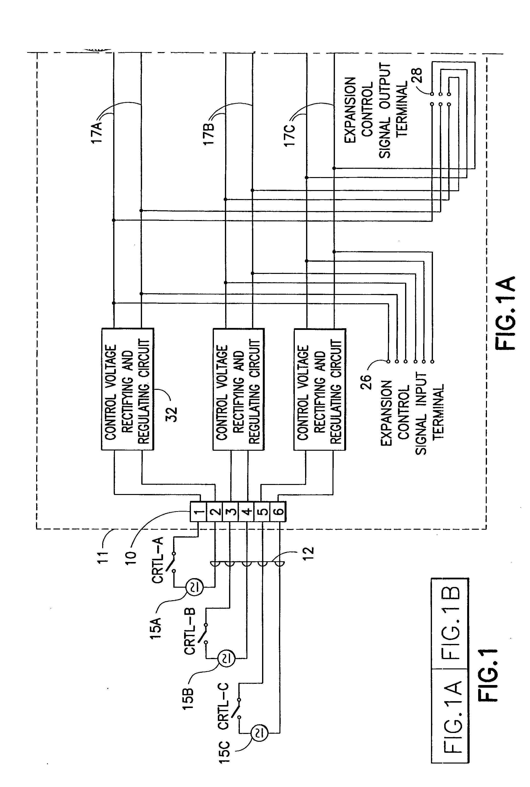
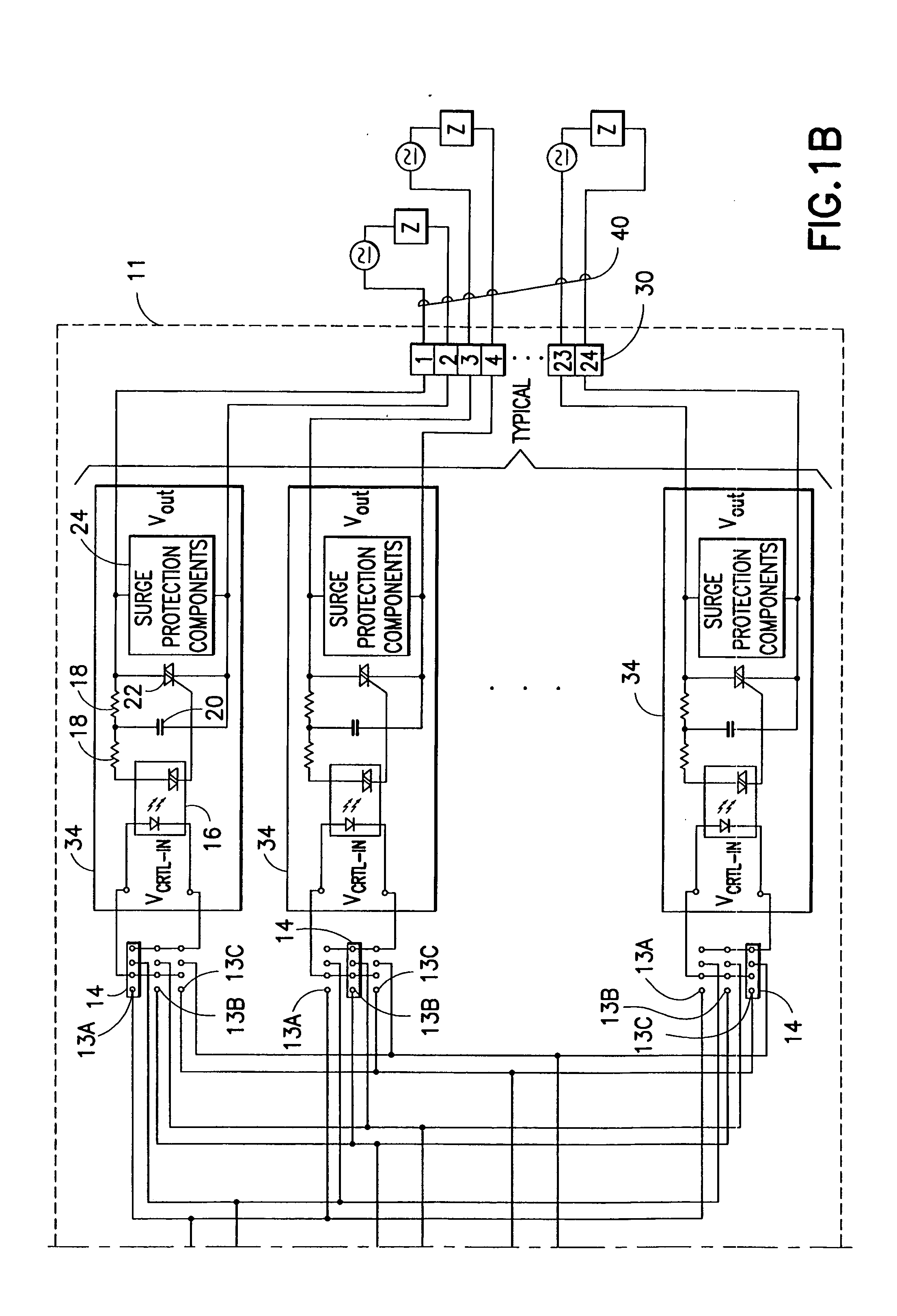
[0024] In the following description, certain representative examples of the solid state multi-pole switching device of the present invention are described with reference to specific types and numbers of components. A first embodiment is described having 3 input control circuits, 12 output circuits, and a pin jumper array for programming the input / output connections, and a second embodiment is described having 4 input control circuits, 16 output circuits, and a CPU with LCD display for programming the input / output connections. However, it should be understood that the invention is not limited in the type and number of switched circuits or input control circuits, or manner of implementing a field-programmable unit for establishing the input / out connections.

[0025] In FIG. 1A, an overall circuit configuration for the first embodiment of the invention has a control signal input terminal strip 10 mounted on a main printed circuit board (PCB) 11 which is connected by connectors 12 to inpu...


PUM


Abstract

A solid state multi-pole switching device has input terminals for a plurality (n) of input control circuits, output terminals for a plurality (m) of output circuits each having an associated solid-state switch unit for switching a respective external circuit load, and a field-programmable unit coupled between the n input control circuits and the m output circuits for selectively establishing an electrical connection of any input control signal to any selected output circuit. The device components are carried on a main circuit board, with the solid state switch units (Triacs) mounted on plug-in boards selectively installed in an array of sockets on the main circuit board. The field-programmable unit may be a simple pin-and-jumper array, or a CPU coupled to an LCD display and settings control device. Timer controls may be programmed through the CPU for automatic on/off switching without the need to manually activate the input control circuits. The device allows a field installer or user to program the desired input/output switching connections onsite, with output circuits being grouped and controlled by input control signals in any desired combination. The device can be used in a wide range of multi-circuit switching control applications such as commercial, industrial or home lighting applications including, but not limited to, stadium lighting, office space lighting, industrial plant lighting, school lighting, home interior or exterior lighting, or store lighting and display.

Description

[0001] This U.S. patent application claims the priority of U.S. Provisional Application No. 60 / 498,724 filed on Aug. 28, 2003, entitled “Solid State Multi-Pole Switching Device With Circuit Grouping”, of the same inventor.TECHNICAL FIELD [0002] This invention generally relates to a solid state switching device, and more particularly, to one which can handle multi-pole switching circuits. BACKGROUND OF INVENTION [0003] Switching devices that employ a mechanical contact to switch power on / off to a circuit are subject to mechanical failure, wear, corrosion, current transients, and other problems that can degrade their performance. For example, U.S. Pat. No. 4,430,579 to D. Wiktor describes a previous type of “Electrically Operated, Mechanically Held Electrical Switching Device”. The switching actuator is solenoid operated with an armature movable between two positions and held in each position by a spring-biased element. It would be desirable to provide an improved switching device tha...

Claims


Application Information

Patent Timeline
Patent Type & Authority Applications(United States)
IPC IPC(8): H01H9/54H05K1/00H05K1/14H05K3/22
CPCH01H9/547H01H2300/04H05K3/222H05K1/14H05K1/0286
Inventor TANIS, JAMES
Owner TANIS JAMES
Why Eureka
Try Eureka