Fuel injector and its control method

Inactive Publication Date: 2005-04-07
HITACHI LTD
View PDF3 Cites 15 Cited by
  • Summary
  • Abstract
  • Description
  • Claims
  • Application Information

AI Technical Summary

Benefits of technology

[0015] According to the present invention, even when power supply voltage changes occur, it is possible to operate the valve body at high speed and stably and to stabilize the amount of fuel in

Problems solved by technology

However, in particular, when the power supply actually

Method used


Image

  • Fuel injector and its control method
  • Fuel injector and its control method
  • Fuel injector and its control method

Examples


Embodiment Construction

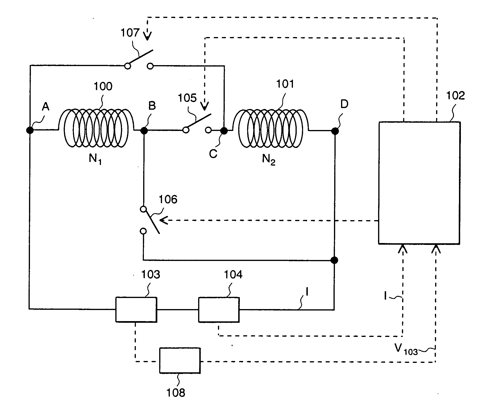
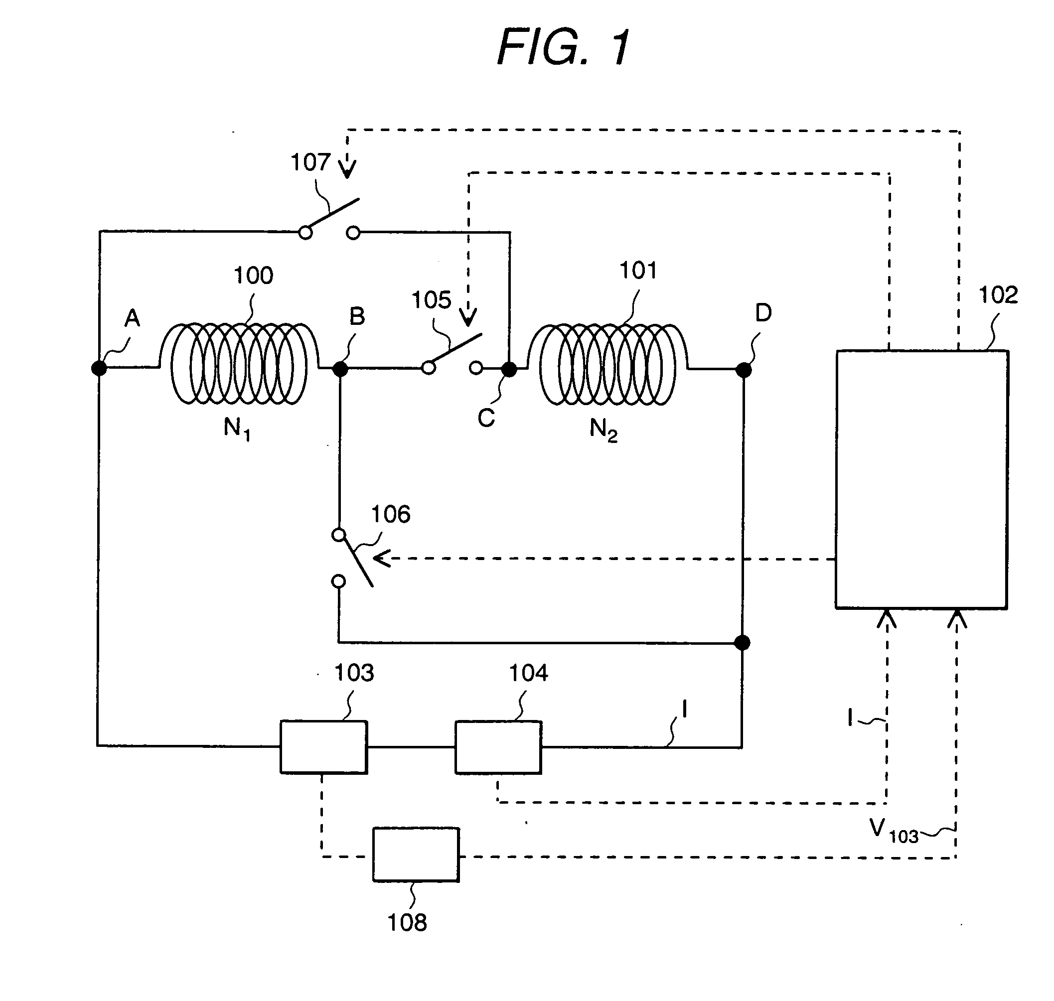
[0027] In a fuel injector system that comprises a direct-current power supply, a power supply voltage detection means, a coil-equipped fuel injection valve, and a control unit for controlling the fuel injection valve, the fuel injection valve has a plurality of coils, and the control unit outputs a changeover signal for changing the magnitude-of-resultant inductance of the plurality of coils of the fuel injection valve in accordance with a power supply voltage detection value received from the power supply voltage detection means.

[0028] The control unit is also adapted to set a reference value of a power supply voltage beforehand and to output a changeover signal by which, when a value that has been detected by the power supply voltage detection means is less than the reference value that has been set beforehand, the resultant inductance of the coils is reduced, and when the power supply voltage detection value is greater than the reference value, the resultant inductance of the co...


PUM


Abstract

When voltage changes occur in the battery used as a power supply in a fuel injection system, the amount of fuel injection also changes and the required amount of fuel injected cannot be obtained. To eliminate this problem, a fuel injector system is provided which has a fuel injection valve with at least one coil, a power supply, a power supply voltage detector, and a control unit for controlling the fuel injection valve. The control unit sets a reference value of a power supply voltages, and the above-mentioned fuel injection valve is controlled so as to obtain the required ampere-turns by reducing the resultant inductance of the coil when a power supply voltage detection value is less than the above-mentioned reference value, and the resultant inductance of the coil is increased when the power voltage detection value is greater than the reference value.

Description

BACKGROUND OF THE INVENTION [0001] The present invention relates to a fuel injector system having a fuel injection valve, which is mounted in an internal-combustion engine to control the amount of fuel supplied to the engine, and to a method of controlling the fuel injection valve. [0002] In general, a fuel injection valve comprises a fuel injection orifice, a valve seat disposed in the vicinity of the fuel injection orifice, a valve body slidably supported in an axial direction at the position facing the valve seat, and a spring. The spring generates a force that presses the valve body in the direction of and into contact with the valve seat so as to close the valve orifice. Thus, while the valve seat and the valve body are kept in contact by the spring force, that is to say, in the closed status of the valve, since the fuel passageway through the fuel injection orifice is closed, fuel is not injected from the fuel injection valve. [0003] The fuel injection valve also has a magneti...

Claims


Application Information

Patent Timeline
IPC IPC(8): F02M51/00F02D41/20F02M51/06
CPCF02D41/20F02D2200/503F02D2041/2079
Inventor MAEKAWA, NORIYUKIABE, MOTOYUKIYAMAKADO, MAKOTOISHIKAWA, TORUSHIBATA, KOOJI
Owner HITACHI LTD
Why Eureka
Try Eureka