Active resonant snubber for dc-dc converter

Active Publication Date: 2005-04-07
DELTA ELECTRONICS INC
View PDF3 Cites 42 Cited by
  • Summary
  • Abstract
  • Description
  • Claims
  • Application Information

AI Technical Summary

Benefits of technology

[0009] It is therefore another object of the present invention to propose a novel and improved active resonant reset

Problems solved by technology

Especially for high frequency and/or high input voltage application, the power loss of the main switch S increases significantly because the energy stored in the capacitor Cr increases with the increase of the switching frequency and the input voltage Vin.
Hence, comparing to resonant rest met

Method used


Image

  • Active resonant snubber for dc-dc converter
  • Active resonant snubber for dc-dc converter
  • Active resonant snubber for dc-dc converter

Examples


Embodiment Construction

[0023] Although this invention is susceptible to embodiments of many different forms, a preferred embodiment will be described and illustrated in detail herein. The present disclosure exemplifies the principle of the invention and is not being considered a limitation to the broader aspects of the invention to the particular embodiment as described.

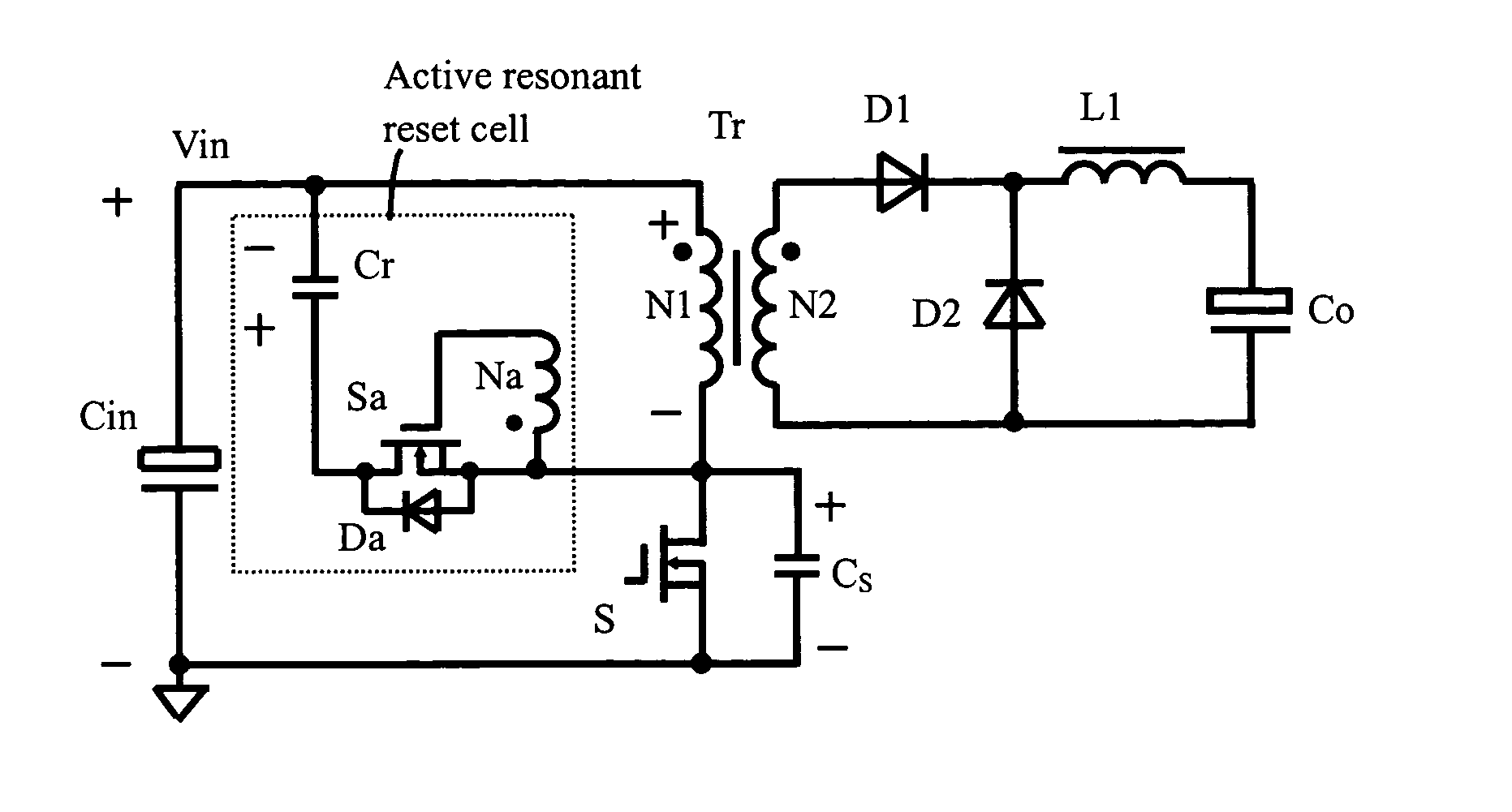
[0024] Please refer initially to FIG. 3A, which is a schematic diagram of an active resonant reset forward DC-DC converter in accordance with present invention. In the active resonant reset forward DC-DC converter, there is a power transformer Tr having a primary winding N1 and a secondary winding N2 isolated the primary side circuit and the secondary side circuit. At the primary side, the primary winding is coupled to an input DC voltage source Vin via a main switch S. An active resonant snubber is connected to the primary winding of the transformer in parallel to reset the transformer Tr. Such active resonant cell is consisted of an act...


PUM


Abstract

The present invention proposes an improved circuit design and configuration of a DC-DC converter with resonant reset. In this present invention, the active resonant snubber in parallel to a primary winding of a transformer of a DC-DC converter for resetting the transformer includes a resonant capacitor, an active switch connected to the resonant capacitor in series, an auxiliary diode coupled across the active switch in parallel, and an auxiliary winding coupled with the transformer. When a main switch of the DC-DC converter is turned off, the auxiliary winding turns on the active switch, and then the transformer is reset by a resonance between a magnetizing inductor of the transformer and the resonant capacitor.

Description

FIELD OF THE INVENTION [0001] The present invention relates to a power supply system and more specifically to an improved circuit design and configuration of a DC-DC converter with resonant reset. BACKGROUND OF THE INVENTION [0002] A single switch forward type DC-DC converter is widely used in the middle and low power conversion occasion due to the simplicity of the structure. For the transformer of a forward DC-DC converter, there are many magnetic reset methods, for example RCD reset, third winding reset, LCD reset, resonant reset, and active clamp reset. The resonant reset and active clamp reset are the most common employed methods because they can realize the bi-directional magnetizing of the transformer core, and obtain the duty cycle larger than 0.5. The bi-directional magnetic current is available for improving the anti-saturation of the transformer core and decreasing the transformer size. Furthermore, the duty cycle larger than 0.5 is available for decreasing the voltage st...

Claims


Application Information

Patent Timeline
IPC IPC(8): H02M1/34H02M3/335
CPCH02M1/34H02M3/33569Y02B70/1491Y02B70/1433H02M2001/342Y02B70/10H02M1/342H02M3/01
Inventor KE, ZHONGWEIXIONG, YAHONGJIN, BINZHANG, ALPHA J.
Owner DELTA ELECTRONICS INC
Why Eureka
Try Eureka