CAS drill guide and drill tracking system

a tracking system and drill technology, applied in the field of drill guide and drill tracking system, can solve the problems of inaccurate representation of the exact three-dimensional (3d) spatial position of the surgical instrument with respect to the patient, inaccurate calculation of the exact three-dimensional (3d) spatial position, etc., and achieve accurate drilling hole location, depth and orientation. accurate

a tracking system and drill technology, applied in the field of drill guide and drill tracking system, can solve the problems of inaccurate representation of the exact three-dimensional (3d) spatial position of the surgical instrument with respect to the patient, inaccurate calculation of the exact three-dimensional (3d) spatial position, etc., and achieve accurate drilling hole location, depth and orientation. accurate

US20050074304A1Active Publication Date: 2005-04-07ORTHOSOFT ULC

Image

  • CAS drill guide and drill tracking system
  • CAS drill guide and drill tracking system
  • CAS drill guide and drill tracking system

Examples


Embodiment Construction

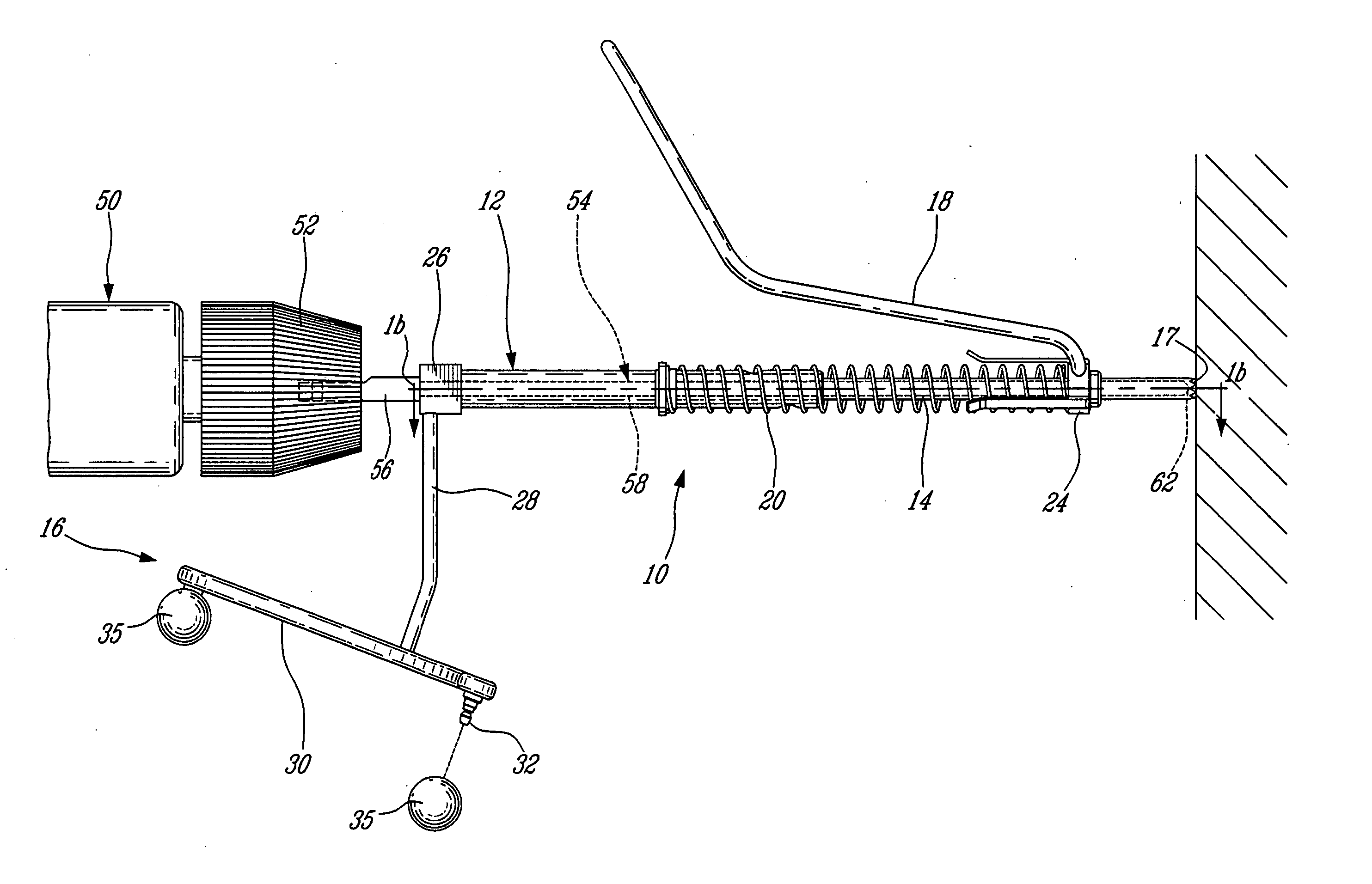
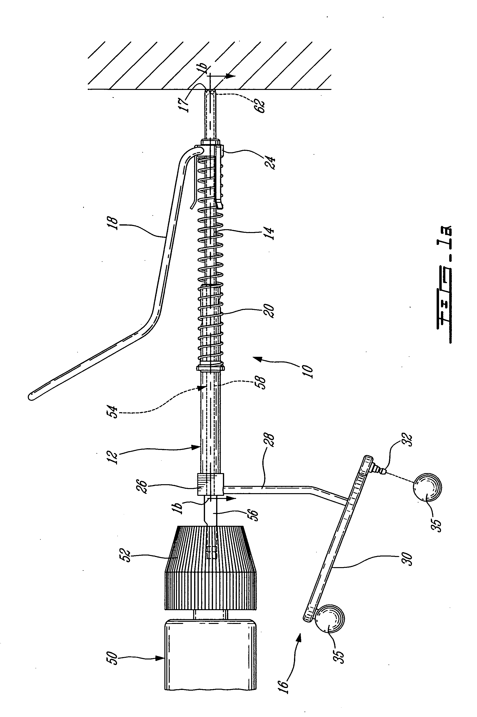
[0034] The computer aided surgery (CAS) drill guide assembly 10 generally comprises a collar member 12, a guide member 14, and a trackable member 16. The guide member 14 is adapted to telescope longitudinally within the sleeve collar member 12.

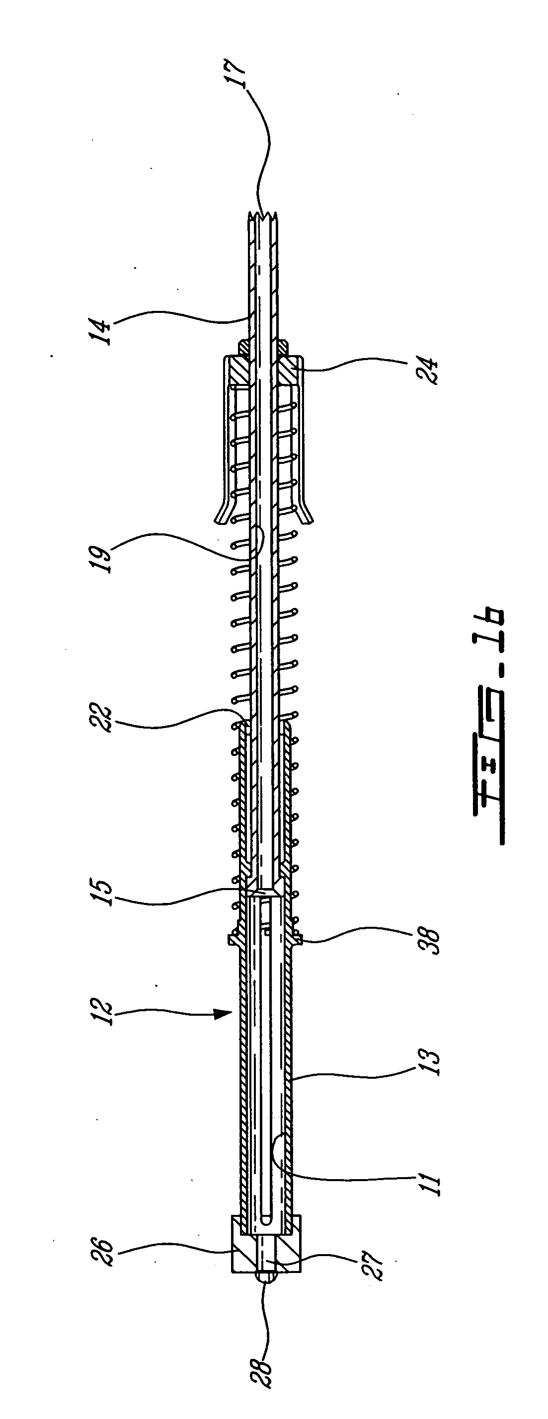
[0035] Referring generally to the assembly shown in FIGS. 1a, 1b and 2, the guide member 14 abuts the workpiece at a proximal end having teeth 17 adapted to frictionally engaged the bone of the patient or other workpiece surface. A chuck portion 52 of a drilling tool 50 retains a drill bit 54 having a distal protrusion 56 which abuts end cap 26 of the collar member 12. Spring 20 generally provides resistance, such that collar member 12 is biased from the guide member 14. The collar member 12 generally defines an inner bore 11, and comprises an outer cylindrical surface 13. A circular flange 38 radially projecting from the outer surface 13 of the collar member 12, provides a reaction point for the spring 20. The end cap 26 fits over the open e...


PUM

PropertyMeasurementUnit
movementaaaaaaaaaa
lengthaaaaaaaaaa
distanceaaaaaaaaaa

Abstract

A drill guide assembly (10) for a drilling tool (50) having a chuck engaging a bit portion (54) comprising a tip (62) and a length extending from the chuck, the drill guide assembly comprising a first member (14), a second member (12) and a trackable member (16). The first member (14) is adapted to abut a workpiece surface and defines a central aperture (19) therethrough adapted to receive the bit portion. The second member (12) is adapted to be axially displaced with respect to the first member and is axially biased therefrom, and defines a central aperture (11) therethrough adapted to receive the bit portion. The trackable member (16), fastened to the second member, comprises a detectable element (35) adapted to be located and tracked in three dimensional space, thereby defining the position and movement of the second member and therefore that of the drilling tool bit portion.

Description

CROSS-REFERENCE TO RELATED APPLICATIONS [0001] This application is a divisional of U.S. patent application Ser. No. 10 / 123,237, filed on Apr. 17, 2002, the entire contents of which is incorporated herein by reference.TECHNICAL FIELD [0002] The present invention relates to surgical devices, and more particularly to a drill guide adapted to provide guidance and tracking of a drilling tool when used in conjunction with a computer aided surgical system. BACKGROUND OF THE INVENTION [0003] Many surgical procedures, particularly those used in orthopaedic surgery, require holes to be drilled in a bone of a patient. Surgical drills have long been used for this purpose, and various mechanical guidance instruments exist to enable a surgeon to accurately drill a hole to a correct depth and without danger of damaging the surrounding tissue. Such drill guides often provide a visual depth gauge which requires the surgeon to read the depth of the drilled hole off a graduated scale on the instrument...

Claims


Application Information

Patent Timeline
07 Apr 2005
Publication
US20050074304A1
IPC
A61B17/17; A61B17/16; A61B19/00
CPC
A61B17/1703; A61B19/50; A61B19/52; A61B19/5244; A61B2019/306; A61B2019/462; Y10T408/564; A61B2019/5227
Inventors
COUTURE, PIERRE; PICARD, DOMINIC