Optical recording medium

a recording medium and optical recording technology, applied in the field of optical recording medium, can solve the problems of inability to achieve sufficient signal amplitude, inability to easily cause pit formation due to thermal deformation of the substrate at the boundary surface between the recording layer and the substrate, etc., to achieve improved optical recording medium, sufficient signal amplitude, and improved recording characteristic

Inactive Publication Date: 2005-04-07
PIONEER CORP
View PDF1 Cites 44 Cited by
  • Summary
  • Abstract
  • Description
  • Claims
  • Application Information

AI Technical Summary

Benefits of technology

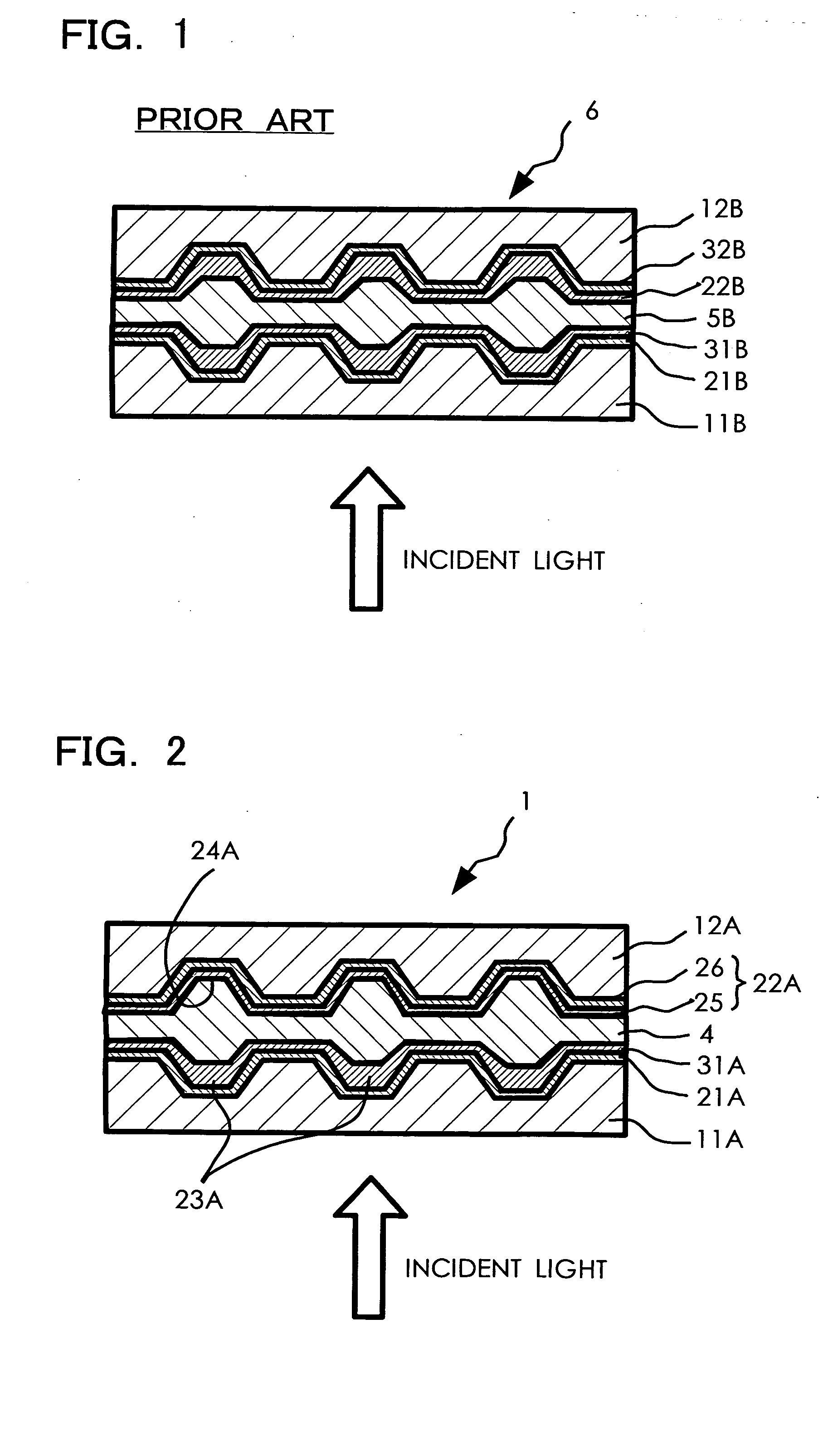
[0012] Therefore, an object of the present invention is to provide an improved optical recording medium. Another object of the present invention is to provide an optical recording medium of dual layer type whereby a recording characteristic is improved for each recording layer, p...

Problems solved by technology

Further, unlike the first recording layer, pit formation due to the thermal deformation of the substrate at the boundary surface between the recordin...

Method used


Image

  • Optical recording medium

Examples


examples

[0056] The optical recording medium of the present invention will be more specifically described below with reference to examples.

Xample 1

[0057] On a disk-shaped first substrate made of polycarbonate with a thickness of 0.6 mm, a wobble groove with a depth of 155 nm, a width of 310 nm, and a track pitch of 0.8 μm was formed in a spiral fashion as a groove, and prepits were formed at predetermined intervals on lands between the wobble grooves.

[0058] On a groove forming surface of the first substrate, coating slip prepared by dissolving and dispersing a metal organic dye, which is composed of a complex of an azo compound, into tetrafluoropropanol was applied by spin coating in order to form a first recording layer with a thickness of 60 nm. Then, on the first recording layer, an Ag—Pd—Cu alloy was formed by sputtering and a reflecting layer was formed with a thickness of 11 nm, so that a first disc was formed.

[0059] Meanwhile, on a disc-shaped second substrate made of polycarbonat...

example 2

[0063] On a disk-shaped first substrate made of polycarbonate with a thickness of 0.6 mm, a wobble groove with a depth of 155 nm, a width of 310 nm, and a track pitch of 0.8 μm was formed in a spiral fashion as a groove, and prepits were formed at predetermined intervals on lands between the wobble grooves.

[0064] On a groove forming surface of the first substrate, coating slip prepared by dissolving and dispersing a metal organic dye, which is composed of a complex of an azo compound, into tetrafluoropropanol was applied by spin coating to form a first recording layer with a thickness of 60 nm. Then, on the first recording layer, an Ag—Pd—Cu alloy was formed by sputtering to form a reflecting layer with a thickness of 11 nm, so that a first disc was formed.

[0065] Meanwhile, on a disc-shaped second substrate made of polycarbonate with a thickness of 0.6 mm, a wobble groove with a depth of 155 nm, a width of 310 nm, and a track pitch of 0.8 μm was formed in a spiral fashion as a gro...


PUM

PropertyMeasurementUnit
Optical reflectivityaaaaaaaaaa

Abstract

An optical recording medium of dual layer type is provided which has at least a first substrate, a first recording layer capable of optical recording, a translucent reflecting layer, an intermediate layer, a second recording layer capable of optical recording, and a second substrate in this order from a side where a laser beam for recording, reproduction, or recording/reproduction is applied, wherein the first recording layer is made of an organic dye and the second recording layer is made of a metal material having a higher reflectivity than the organic dye. The optical recording medium provides sufficient signal amplitudes from both recording layers during reproduction, and gives compatibility with a typical optical recording medium during reading.

Description

BACKGROUND OF THE INVENTION [0001] 1. Field of the Invention [0002] The present invention relates to an optical recording medium. More particularly, the present invention relates to improvement in a recording characteristic for each recording layer in a writable optical recording medium of a double layer structure. [0003] 2. Description of the Related Art [0004] Optical recording mediums such as a DVD (digital versatile disc) are conventionally known as recording mediums for recording and reproducing various kinds of information. The known optical recording mediums include an optical recording medium of single layer type which has a layer for recording information from one side, and an optical recording medium of dual layer type which has two layers for recording information from one side. [0005] Of these optical recording mediums, the optical recording medium of dual layer type has two layers for recording information (the layers for recording information are hereinafter simply ref...

Claims


Application Information

Patent Timeline
IPC IPC(8): B41M5/26B32B27/36G11B7/24027G11B7/24035G11B7/24041G11B7/243G11B7/244
CPCB32B27/36G11B7/24038G11B7/243G11B7/246G11B2007/2432G11B7/258G11B2007/24306G11B2007/24312G11B2007/24314G11B7/2467
Inventor TAKISHITA, TOSHIHIKOKURODA, KAZUOSUZUKI, TOSHIOMURAMATSU, EIJIKATO, MASAHIROOSHIMA, SEIROKONDO, ATSUSHI
Owner PIONEER CORP
Why Eureka
Try Eureka