
Solid oxide fuel cell stack configuration

Inactive Publication Date: 2005-04-07
CERAMIC FUEL CELL LTD
View PDF26 Cites 19 Cited by
  • Summary
  • Abstract
  • Description
  • Claims
  • Application Information

AI Technical Summary

Benefits of technology

[0011] Provision of fuel inlet and exhaust manifolds internally of the plates and oxygen-containing gas (usually air) inlet and exhaust manifolds externally of the plates can optimise the structure of the plates from both economic and power producing perspectives. If the manifolds were fully internalised, the construction of the plates would be more complex and a significant portion of the plates would need to be dedicated to the formation of the respective manifolds, i.e. each plate would have an increased aperture area compared to the plates in the stack of the invention. Relatively increasing the functional area of the plates allows for maximised generation of electric current from the stack. Externalising the air manifolds simplifies the inter-plate sealing since there are no air apertures through the plates around which individual seals must be provided, and providing the air manifolds between the plates and the housing can allow for simple seals between the air manifolds. However, internalising the fuel manifolds also means the overall structure may be robust since external connections which may otherwise be subject to fatigue or leakage are minimised.
[0014] It is important that the incoming and exhaust air is prevented from leaking into the anode sides of the fuel cell plates, and there is advantageously provided a respective gas-tight seal between said one of each fuel cell plate and the adjacent gas separator plate around said plates outwardly of the apertures of said series of apertures through said plates. This gas-tight seal may extend wholly around the periphery of the one side of the respective fuel cell plate and adjacent gas separator plate, but conveniently it is also used to direct the fuel gas flow across the anode.

Problems solved by technology

While planar solid oxide fuel cells are a proven technology in terms of individual cells, the problem of combining the individual cells into stacks, having collectively useful power at reasonable cost and with acceptable durability, has proven to be an elusive goal to those skilled in the art.
Specific difficulties include providing satisfactory fuel and oxygen-containing gas inlet and exhaust manifolding systems as well as reliable sealing of the system at a commercially acceptable cost while at the same time providing a structure that is robust to thermal cyling.
However, there is no suggestion of how this is achieved.

Method used


Image

  • Solid oxide fuel cell stack configuration
  • Solid oxide fuel cell stack configuration
  • Solid oxide fuel cell stack configuration

Examples


Embodiment Construction

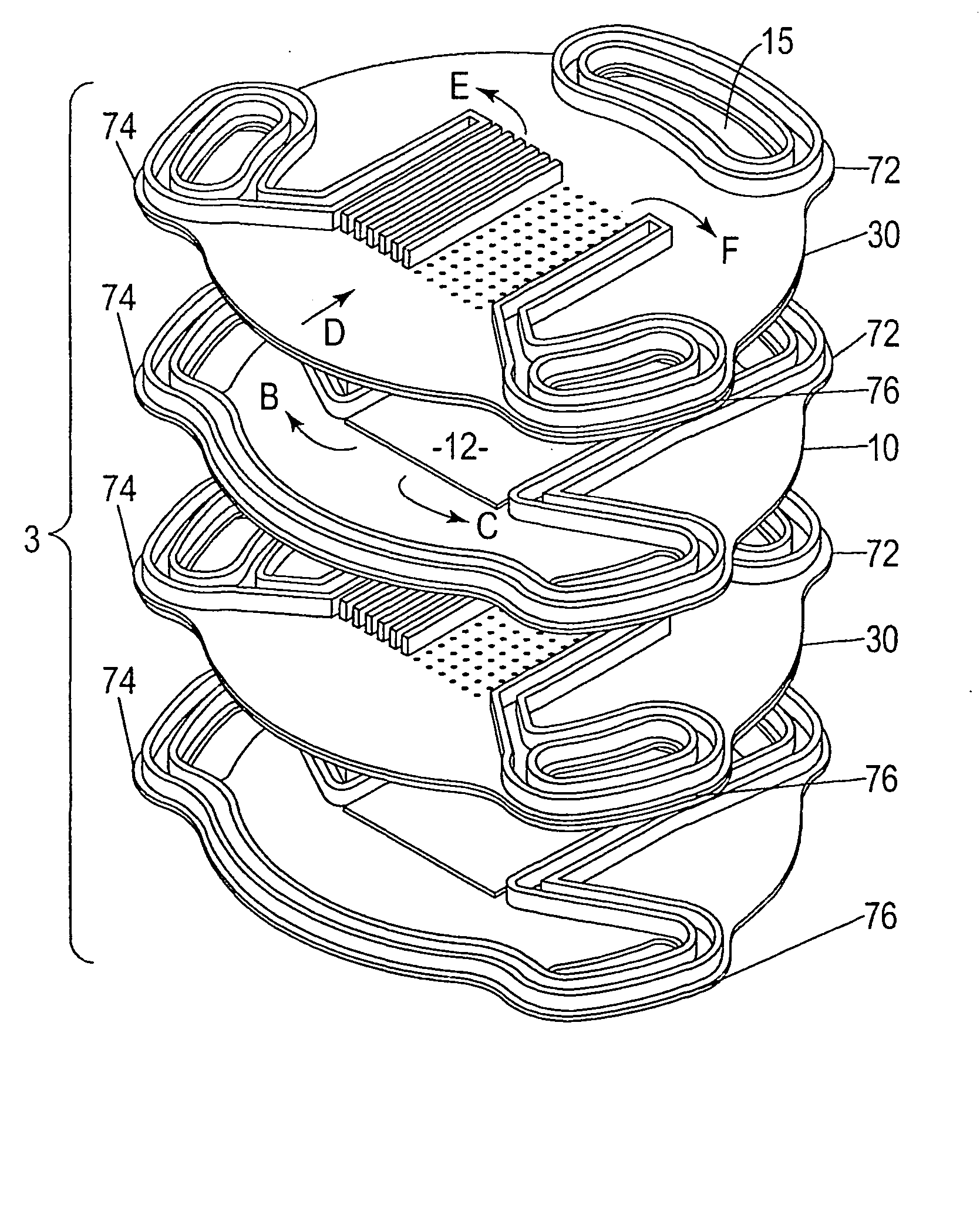
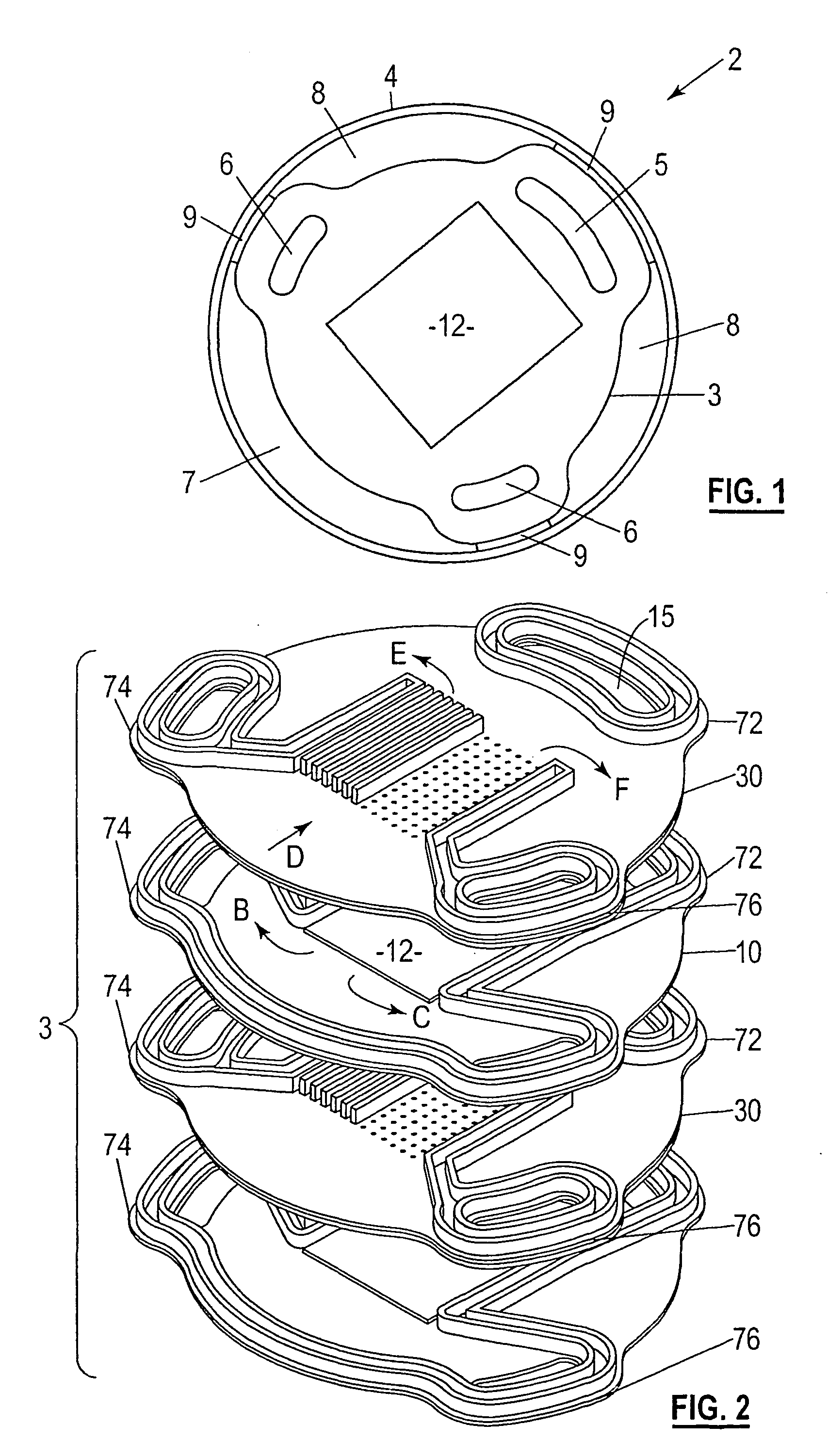
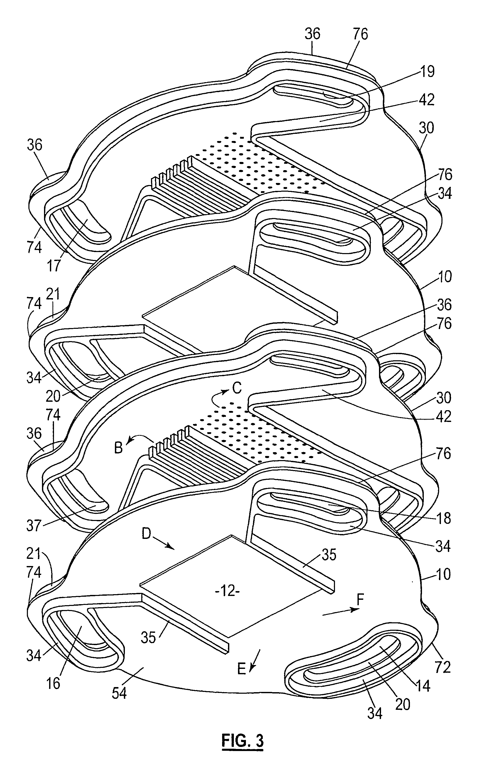
[0031] Referring to FIGS. 1, 2 and 3 a solid oxide fuel cell stack assembly 2 comprises a stack 3 of alternating fuel cell components, in the form of cell plates 10 and gas separator plates 30 held within a tubular housing 4. All of the cell plates 10 are identical and all of the separator plates 30 are identical. Typically there might be 20 to 500 of each of these plates in the stack 3. Fuel gas and air are supplied at one axial end of the stack assembly and exhaust gases are collected at the other end in a co-current manifolding system. Either end is suitable for the supply and exhaust functions, but the manifold system may alternatively be counter-current. In the described co-current embodiment, the fuel and air supplies are both at the bottom and the exhausts are at the top, but in many circumstances it is preferred for the fuel to be supplied from the bottom and the air to be supplied from the top in a counter-current arrangement. Alternatively, all of the gas supplies and exha...


PUM


Abstract

A fuel cell stack (2) comprises a stack (3) of alternating solid oxide fuel cell and gas separator plates within a housing (4). Each fuel cell plate has apertures therethough aligned with corresponding apertures through adjacent separator plates. A first aligned series of apertures in the fuel cell and separator plates opens to the anode side of each fuel cell to form a first manifold (5) for incoming fuel gas. A second aligned series of apertures in the fuel cell and separator plates opens from the anode side of each fuel cell to form a second manifold (6) for exhaust fuel gas. A third manifold (7) for in coming air is formed between the stack (3) and housing (4) and opens to the cathode side of each fuel cell. A fourth manifold (8) for exhaust air is formed between the stack (3) and housing (4) and opens from the cathode side of each fuel cell. In a preferred embodiment a third aligned series of apertures in the plates opens from the anode side of each fuel cell to form a second exhaust fuel gas manifold (6) and a second exhaust air manifold (8) is formed between the stack (3) and housing (4). Sliding fibrous seals (9) are provided are provided between the stack (3) and housing (4) to separate the air manifolds (7) and (8).

Description

FIELD OF THE INVENTION [0001] The present invention relates to a solid oxide fuel cell (SOFC) stack configuration. In particular, the invention concerns the arranging of planar SOFCs into a stack with improved manifolding. BACKGROUND OF THE INVENTION [0002] While planar solid oxide fuel cells are a proven technology in terms of individual cells, the problem of combining the individual cells into stacks, having collectively useful power at reasonable cost and with acceptable durability, has proven to be an elusive goal to those skilled in the art. Specific difficulties include providing satisfactory fuel and oxygen-containing gas inlet and exhaust manifolding systems as well as reliable sealing of the system at a commercially acceptable cost while at the same time providing a structure that is robust to thermal cyling.[0003] There have been many different patent proposals for manifolding fuel cell systems comprising alternating fuel cell members and gas separator members, both for SO...

Claims


Application Information

Patent Timeline
IPC IPC(8): H01M4/00H01M8/04089H01M8/241H01M8/2425H01M8/2475H01M8/2485H01M50/10
CPCH01M8/04089H01M8/2415Y02E60/50H01M8/2475H01M8/2485H01M8/2425H01M8/2483H01M8/0271
Inventor THOMAS, STEPHEN ROGER MAITLANDO'HARA, ANTHONY GRAHAMHICKBY, DARREN BAWDENLE, YEESANLAWRENCE, JEREMY CARLKISTAS, ARTHUR
Owner CERAMIC FUEL CELL LTD
Learn More