
Robotic physical distribution tracking system

a tracking system and robot technology, applied in the field of robot physical distribution tracking system, can solve the problems of reducing efficiency, reducing the number of robots, and the operation speed of the robot has an upper limit, so as to reduce the waiting time of each robot, rationally carry out, and handle the workpiece more efficiently

Inactive Publication Date: 2005-04-07
FANUC LTD
View PDF4 Cites 92 Cited by
  • Summary
  • Abstract
  • Description
  • Claims
  • Application Information

AI Technical Summary

Benefits of technology

The present invention provides a robotic physical distribution tracking system that can efficiently handle workpieces conveyed on a feeding conveyor. The system includes a workpiece position detection means and a conveyor moving amount detection means to track the workpiece and determine its position. A plurality of robots are placed along the feeding conveyor to handle the workpieces. A workpiece distribution control means determines which robot can handle a workpiece based on its position, the robot's operating speed, and the conveyor's moving speed. The system can also adjust the conveyor speed to reduce waiting time for each robot and improve efficiency. Overall, the system allows for a more efficient and effective tracking operation.

Problems solved by technology

However, the operating speed of the robot has an upper limit, and therefore, the only way in many cases is to increase the number of robots.
However, when the articles are conveyed at irregular intervals, the upstream robot sometimes enters the waiting state even if the upstream robot can hold articles, thereby resulting in a reduced efficiency.
However, as the operation of the robot to hold the article is reserved based on the operable period of the particular robot, a change in the cycle time due to the change in the robot operation route sometimes requires the reservation to be changed, thereby increasing the processing load on the operation reservation unit.

Method used


Image

  • Robotic physical distribution tracking system
  • Robotic physical distribution tracking system
  • Robotic physical distribution tracking system

Examples


Embodiment Construction

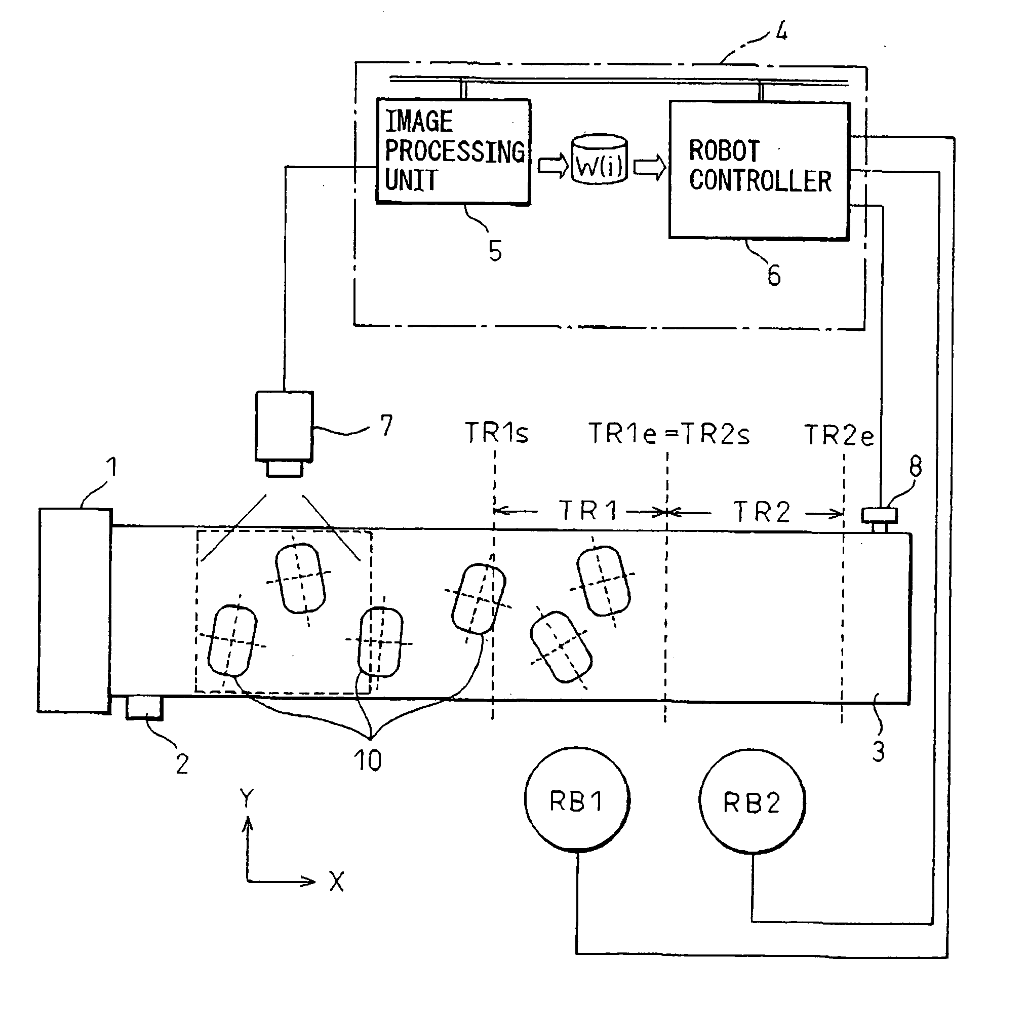
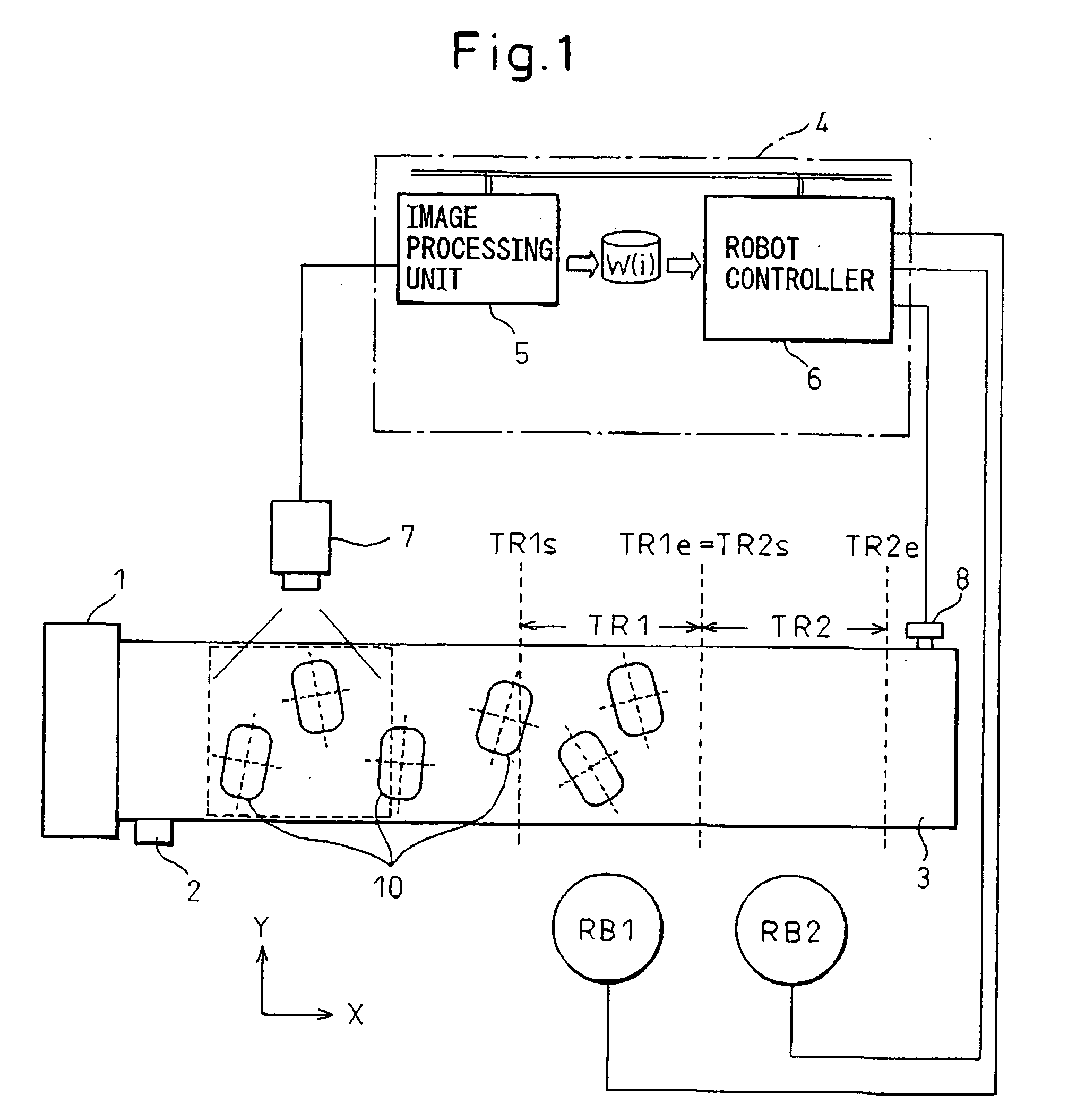
[0022] With reference to FIG. 1, a robotic physical distribution tracking system according to an embodiment of the present invention is shown.

[0023] In this embodiment, two robots RB1, RB2 for performing a tracking operation are disposed along a feeding direction of a feeding conveyor. A term “tracking operation” means handling a workpiece 10 conveyed on the feeding conveyor 3 while at the same time tracking the workpiece 10 constituting an object of operation and conveyed on the feeding conveyor 3. Further, a visual sensor is provided as a workpiece position detection means for the tracking operation. The visual sensor has an image processing unit 5 and a camera 7 connected to the image processing unit 5, and the image processing unit 5 processes an image provided by the camera 7 thereby to detect a position of a workpiece 10. A workpiece supply unit 1 continuously supplies a multiplicity of workpieces 10 constituting objects of the operation. At that time, the workpieces 10 are p...


PUM


Abstract

An image of a workpiece (10) conveyed by a feeding conveyor (3) is taken by a camera (7) of a visual sensor to detect a position of the workpiece. The moving amount of the feeding conveyor (3) is detected by a pulse coder (8). When a request for picking up a workpiece is issued to a plurality of robots (RB1, RB2), it is judged whether or not the robots can grip the workpiece positioned most downstream, based on current positions of the robots and a current position of the workpiece. The workpiece should be gripped before it reaches the downstream boundary line (TR1e, TR2e) in the tracking range of the robot. If the workpiece can be gripped, the robot picks up the workpiece. Based on the robot operating speed, the feeding speed of the feeding conveyor (3) is adjusted to reduce the waiting time of the plurality of robots (RB1, RB2) and to reduce the number of failures to hold the workpiece as far as possible.

Description

BACKGROUND OF THE INVENTION [0001] 1. Field of the Invention [0002] The present invention relates to a physical distribution tracking system for transferring articles from a feeding conveyor to other positions using a robot. [0003] 2. Description of the Related Art [0004] Conventionally, a robotic physical distribution tracking system in which a plurality of robots arranged along a feeding line of a feeding conveyor hold, for example, by gripping or sucking, articles conveyed by the feeding conveyor and transfer the held articles from the feeding conveyor to other positions is known as an article handling system using a visual sensor and an industrial robot. [0005] In the case that a multiplicity of articles are conveyed on the feeding conveyor and are picked up from the conveyor by a plurality of the robots in such a robotic physical distribution tracking system, the plurality of robots are required to be operated efficiently. [0006] In order to solve this problem, a system is sugg...

Claims


Application Information

Patent Timeline
Patent Type & Authority Applications(United States)
IPC IPC(8): G01B11/00B25J13/00B25J13/08B65G47/90G01B21/00G05B19/418
CPCG05B19/4182B25J9/1697Y02P90/02
Inventor BAN, KAZUNORIJYUMONJI, TAKASHI
Owner FANUC LTD
Learn More