Trimmer head for use in flexible line rotary trimmers having improved line loading mechanism

a technology of flexible line rotary trimmer and trimmer head, which is applied in the field of improved trimmer head, can solve the problems of no longer ensuring positive engagement, time-consuming task for professional users, and difficulty in properly loading the line on the spool, so as to facilitate line loading, facilitate the loading of the head with cutting lines, and easily orient the spool

Active Publication Date: 2005-04-14
PROULX MFG
View PDF19 Cites 30 Cited by
  • Summary
  • Abstract
  • Description
  • Claims
  • Application Information

AI Technical Summary

Benefits of technology

[0011] In operation, the drive motor on the trimmer rotates the trimmer housing and cam member in a first direction that is imparted to the cam follower as a result of the abutment of the cam surfaces on the lower cam with the trailing cam abutment surfaces on the cam follower. Corresponding rotation of the spool is effected by the projection of the engagement lugs on the cam follower in the slots in the inner spool wall. Upon the cutting head being bumped upon the ground, a 45° rotation of the cam relative to the cam follower is effected and a subsequent 45° rotation occurs upon the head being released from the ground so as to effect a relative rotation of 90° between the spool and the housing and the paying out of predetermined lengths of fresh cutting line with each bump of the head upon the ground, regardless of the duration of the bump.
[0012] To facilitate loading the head with cutting line, the spool is provided with tapered line receptor channels, polygonal in cross-section, that project radially into an upper spool flange and are adapted to be radially aligned with the outlet eyelets in the housing wall by rotating the spool relative to the housing. Upon inserting the end portion of a length of cutting line through each of the eyelets and pushing the line firmly into the aligned receptor channels, the line will be securely held in place by the tapered channel walls when pulled at an acute angle back toward the spool. Thus, by holding the housing stationary and rotating the spool in the same direction as the spool rotates in the drive mode, the secured lengths of line will be wrapped about the rotating spool, obviating the need to separate the spool from the housing for line loading purposes.
[0013] To provide an even distribution of the lengths of cutting line about the spool and prevent tangling within the spool, the trailing surfaces on the lower cam that are adjacent and perpendicular to the cam surfaces thereon and the leading surfaces on the abutment members on the cam follower are oppositely inclined such that rotation of the spool in the drive direction while holding the housing stationary will cause the inclined leading surfaces on the abutment members on the cam follower to periodically abut and slide upwardly along and over the trailing surfaces on the lower cam, compressing the coil spring. Once the cam surfaces clear the cam abutment members, the coil spring will force the cam follower downwardly, realigning the cam abutment surfaces with the lower cam. As a result, continual manual rotation of the spool relative to the housing will wrap the lines about the spool while providing a vertical reciprocating or ratcheting effect of the spool with respect to the housing as the line is wrapped thereon so that the line is uniformly disposed about the spool. Printed indicia are preferably molded into the upper surface of the spool to allow the user to easily orient the spool relative to the housing such that the receptor channels are radially aligned with the exit apertures in the housing enabling the line to be readily inserted through the eyelets and into the receptor channels to load the line about the spool.
[0014] The line receptor channels and spool ratcheting mechanism of the present invention that facilitate line loading can also be utilized in other bump and feed head configurations and in manual heads. In each case, the line receptors are provided on the spool flange radially alignable with the outlet eyelets in the housing. In a bump-feed head such as that disclosed in U.S. Pat. No. 4,959,904 at least the trailing surfaces on the lower cam follower that is defined by lower outer radial surfaces of the spool is inclined such that rotation of the spool in the drive direction while maintaining the housing in a stationary disposition will cause the spool to periodically ratchet upwardly and downwardly within the housing as the line is drawn inwardly through the eyelets and wrapped about the spool to effect an even distribution of the lengths of line about the spool within the housing. The leading radial surfaces of the lower cam follower and the trailing surfaces of the cams formed by the upper and lower portions of the housing may also be inclined to provide a smoother ratcheting movement for the head during the winding of the line onto the spool.
[0015] In a manual feed head such as that disclosed in U.S. Pat. No. 4,145,809, a plurality of pins or drive lugs are disposed about and project upwardly from the upper surface of the spool and project into correspondingly sized and spaced apertures in the upper surface of the housing such that rotation of the housing will effect corresponding rotation of the spool. By providing radially alignable line receptors in the spool flange and ramping the interior upper surface of the housing between each of the apertures therein, the line ends can be inserted through eyelets into the receptor channels and gripped by the spool so that rotation of the spool relative to the housing as above described will cause the lugs on the spool to repeatedly travel downwardly along adjacent ramps and snap upwardly into the next aperture. Continued relative rotation will thus effect the desired reciprocating motion of the spool within the housing to evenly distribute the cutting line about the spool.

Problems solved by technology

Difficulty in properly loading the line on the spool is the most common complaint of home users of flexible line trimmers.
It also is a time consuming task for the professional user.
However, friction within such devices and overzealous bumping often resulted in two or more line segments being fed out, particularly especially when the device has been in use and the corners on the ribs and tangs became worn such that positive engagement was no longer assured.
The unavoidable abrupt operation of the dog clutch caused such wear to occur.
Because of early difficulties in molding some of the components of the cutting head disclosed in U.S. Pat. No. 4,458,419, the head became more expensive to manufacture than anticipated.
Over the years, with increasing competition from offshore manufacturers, it became clear that even with the development of new materials the earlier bump-feed mechanism covered by U.S. Pat. No. 4,459,419 was not as economical to manufacture as earlier believed.
In addition, vibration, the threaded engagement between the cam member and the drive bolt, and the heat generated by the trimmer required the use of a chemical bonding agent having a high melting point to prevent the cam member and cam follower from breaking loose from the drive bolt.
Such agents, however, had extremely high break way torques, rendering the threaded connection effectively permanent.
As a result, certain components of the head could not be replaced when worn.

Method used


Image

  • Trimmer head for use in flexible line rotary trimmers having improved line loading mechanism
  • Trimmer head for use in flexible line rotary trimmers having improved line loading mechanism
  • Trimmer head for use in flexible line rotary trimmers having improved line loading mechanism

Examples


first embodiment

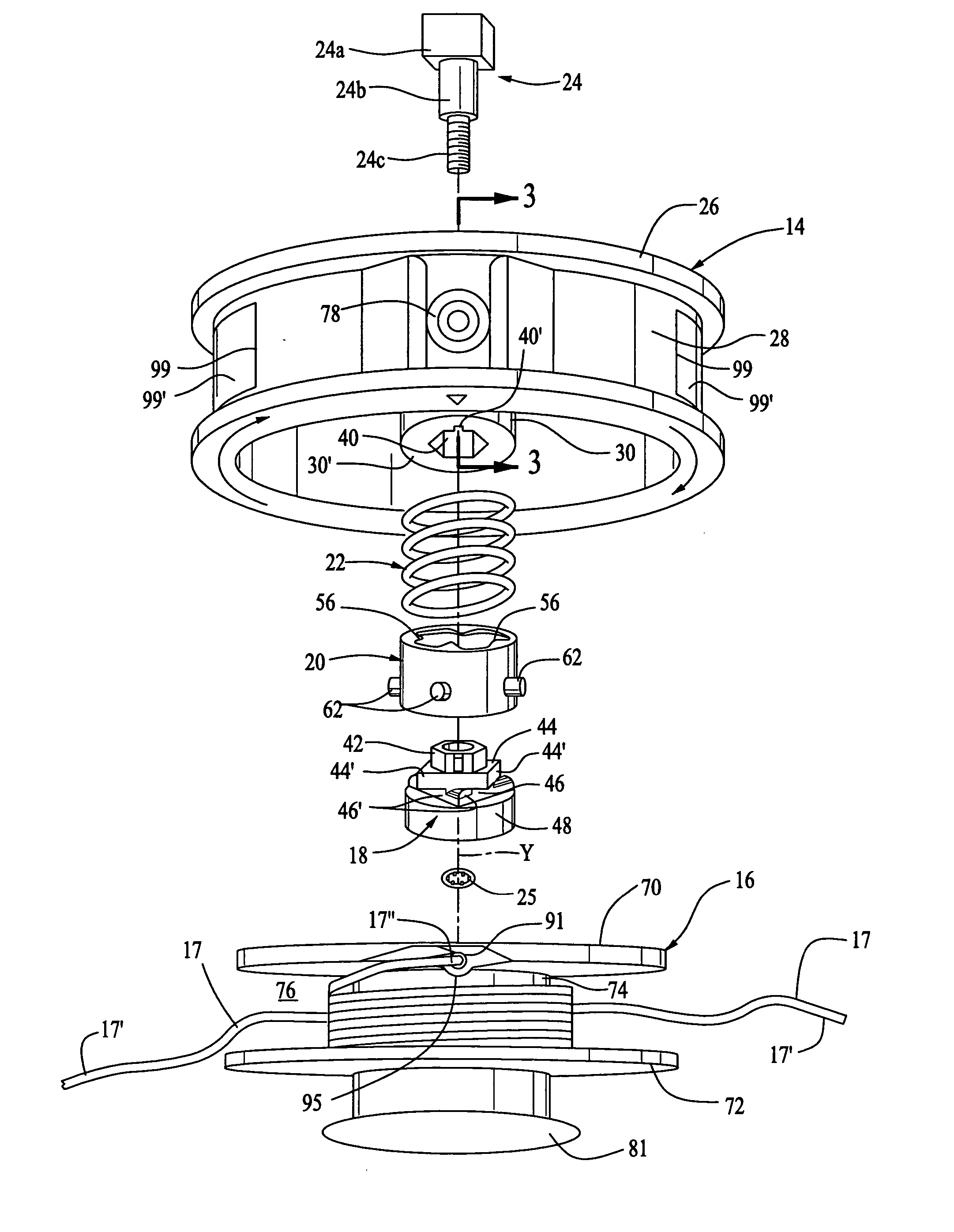
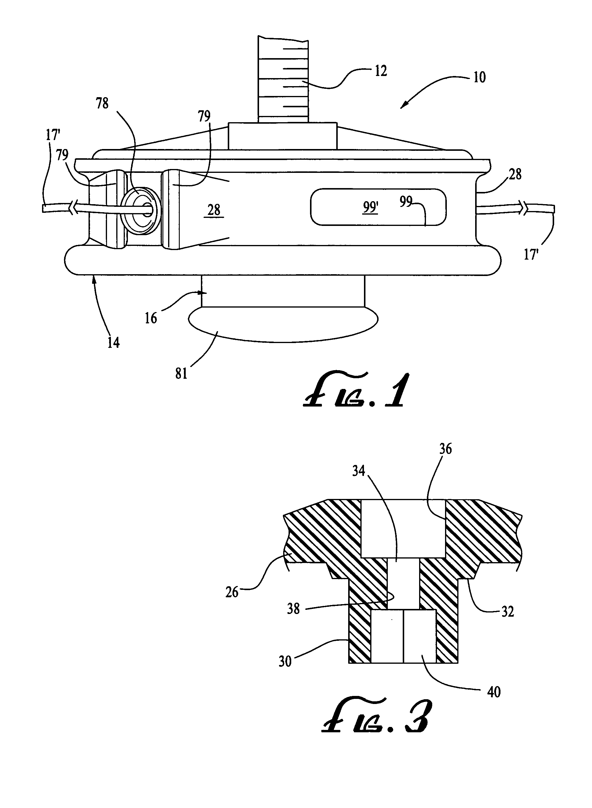
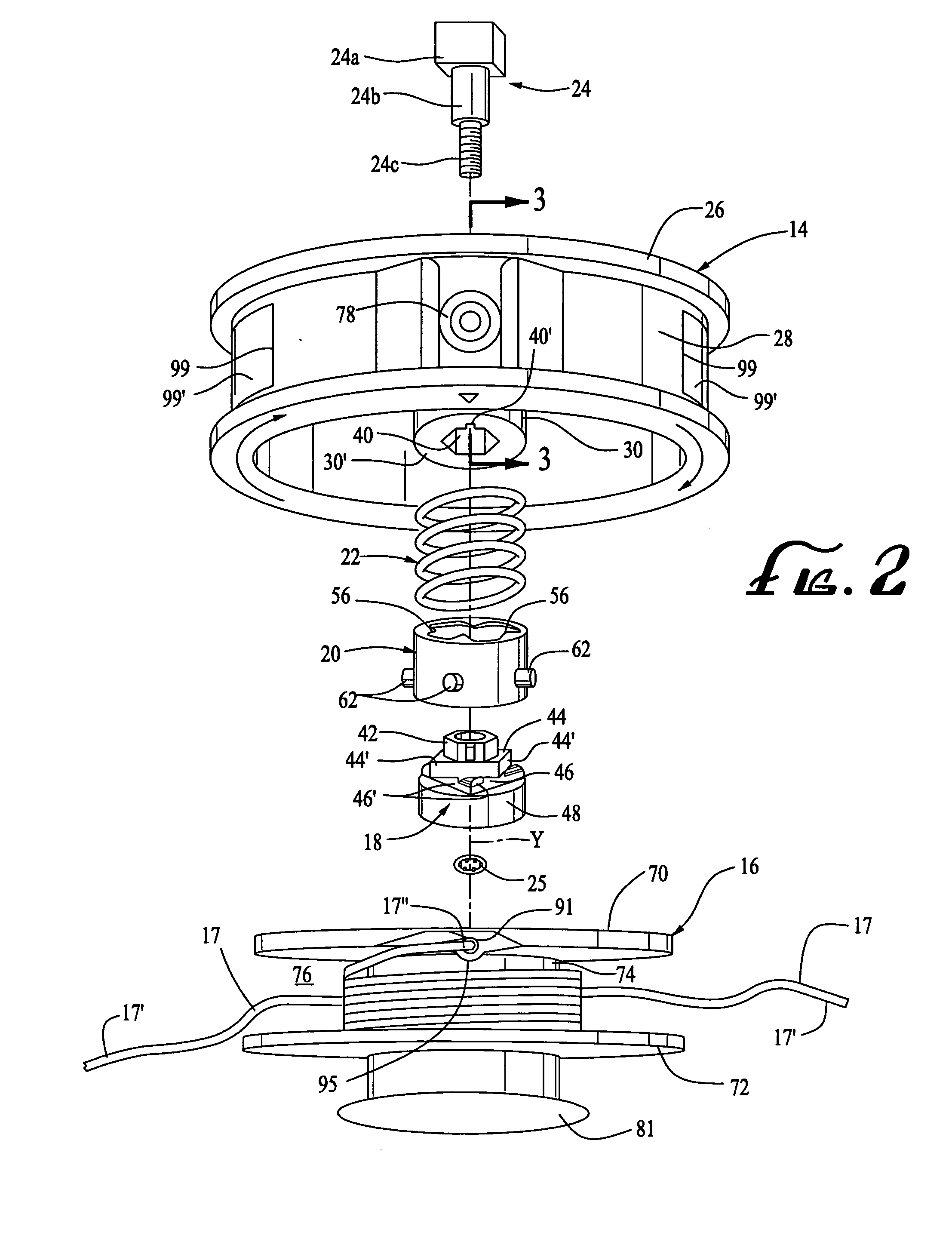
[0066] Referring now in detail to the drawings, a bump-feed type trimmer head 10 of the present invention is shown in FIG. 1 mounted on the extended end of a rotatable drive shaft 12 on a gasoline or electric powered rotary trimmer (not shown). The trimmer head 10 generally comprises a housing 14, a spool 16 for carrying one or more lengths of coiled monofilament nylon cutting line 17, a cam member 18, a cam follower 20, a coil spring 22, a drive bolt 24 and a retaining nut 25. The trimmer housing 14 is preferably formed by injection molding a nylon 6 copolymer and defines a circular upper wall 26, a cylindrical depending skirt 28 and a centrally disposed tubular extension 30 depending from upper housing surface 26 into the interior of the housing about the central axis of rotation “Y” of the head. The tubular extension 30 in the trimmer head housing 14 defines an annular outer shoulder 32 for coil spring 22 and an axial channel 34 through which the drive bolt 24 extends. Channel 34...

second embodiment

[0096] the present invention is illustrated in FIGS. 20-31 wherein the line loading mechanism is employed in a manual trimmer head 100. Head 100 is also mounted on the extended end of a rotatable drive shaft on a gasoline or electric powered rotary trimmer. The trimmer head 100 generally comprises a housing 114, a spool 116 for carrying one or more lengths of coiled monofilament nylon cutting line 17, a coil spring 122, drive bolt 124 and a wing nut 125 for securing the spool 116 to the trimmer head housing 114.

[0097] The trimmer housing and spool are preferably formed of the same material as the corresponding components of the prior embodiment. The housing 114 defines an upper circular wall 126, a cylindrical skirt 128 depending therefrom and a centrally disposed tubular extension 130. Extension 130 is axially aligned with the central axis of rotation “Y” of the head and includes a depending portion 130a and an upwardly projecting portion 130b. The tubular extension 130 is configur...


PUM


Abstract

A trimmer head for use in a flexible line rotary trimmer including a housing adapted to be operatively connected to the trimmer to effect rotation of the head and a spool operatively connected to the housing for rotation therewith. The spool defines at least one line radially extending receptor channel formed by a plurality of inwardly tapered walls and is polygonal in cross-section. So configured, the channel walls will securely grip the cutting line upon the line being inserted in the channel and wound about the spool. To provide uniform winding of the line, a plurality of cam, cam abutment and sliding surfaces are operatively connected to the housing and spool such that when the spool is manually rotated relative to the housing in the drive direction, the spool is caused to reciprocate axially within the housing evenly distributing the line about the body of the spool.

Description

CROSS-REFERENCE TO RELATED APPLICATIONS [0001] This is a continuation-in-part of U.S. patent application Ser. No. 10 / 677,700, filed Oct. 2, 2003, and entitled “Trimmer Head for Use in Flexible Line Rotary Trimmers.”BACKGROUND OF THE INVENTION [0002] The present invention relates to an improved trimmer head for use in flexible line rotary trimming devices used to trim grass, weeds and other vegetation. More particularly, the invention is directed to an improvement in the line loading of both “bump-feed” type trimmer heads such as those disclosed in U.S. Pat. Nos. 4,458,419 and 4,959,904 and the more simple manually operated heads such as that disclosed in U.S. Pat. No. 4,145,809, the contents of said patents being incorporated herein by reference as though fully set forth below. [0003] Trimmer heads used in flexible line rotary trimmers generally carry one or two lengths of flexible nylon cutting line wrapped about an interior spool with the ends of the line or lines projecting outwa...

Claims


Application Information

Patent Timeline
Patent Type & Authority Applications(United States)
IPC IPC(8): A01D34/416
CPCA01D34/4163
Inventor PROULX, RICHARD A.
Owner PROULX MFG
Why Eureka
Try Eureka