Electrochemical device and gas storage apparatus

Inactive Publication Date: 2005-04-14
SONY CORP
View PDF6 Cites 14 Cited by
  • Summary
  • Abstract
  • Description
  • Claims
  • Application Information

AI Technical Summary

Benefits of technology

[0011] It is an object of the present invention to provide a new pressure reducing device, an electrochemical device, a pressure reducing and pressurizing device, a gas storage device and a g

Problems solved by technology

Further, since the above-described gas regulator has movable parts, an abrasion due to a friction is genera

Method used


Image

  • Electrochemical device and gas storage apparatus
  • Electrochemical device and gas storage apparatus
  • Electrochemical device and gas storage apparatus

Examples


Embodiment Construction

[0055] Now, embodiments of the present invention will be described by referring to the drawings.

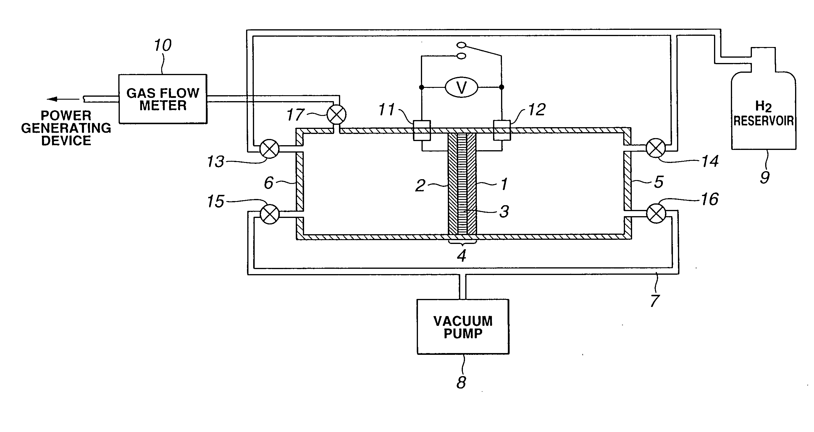
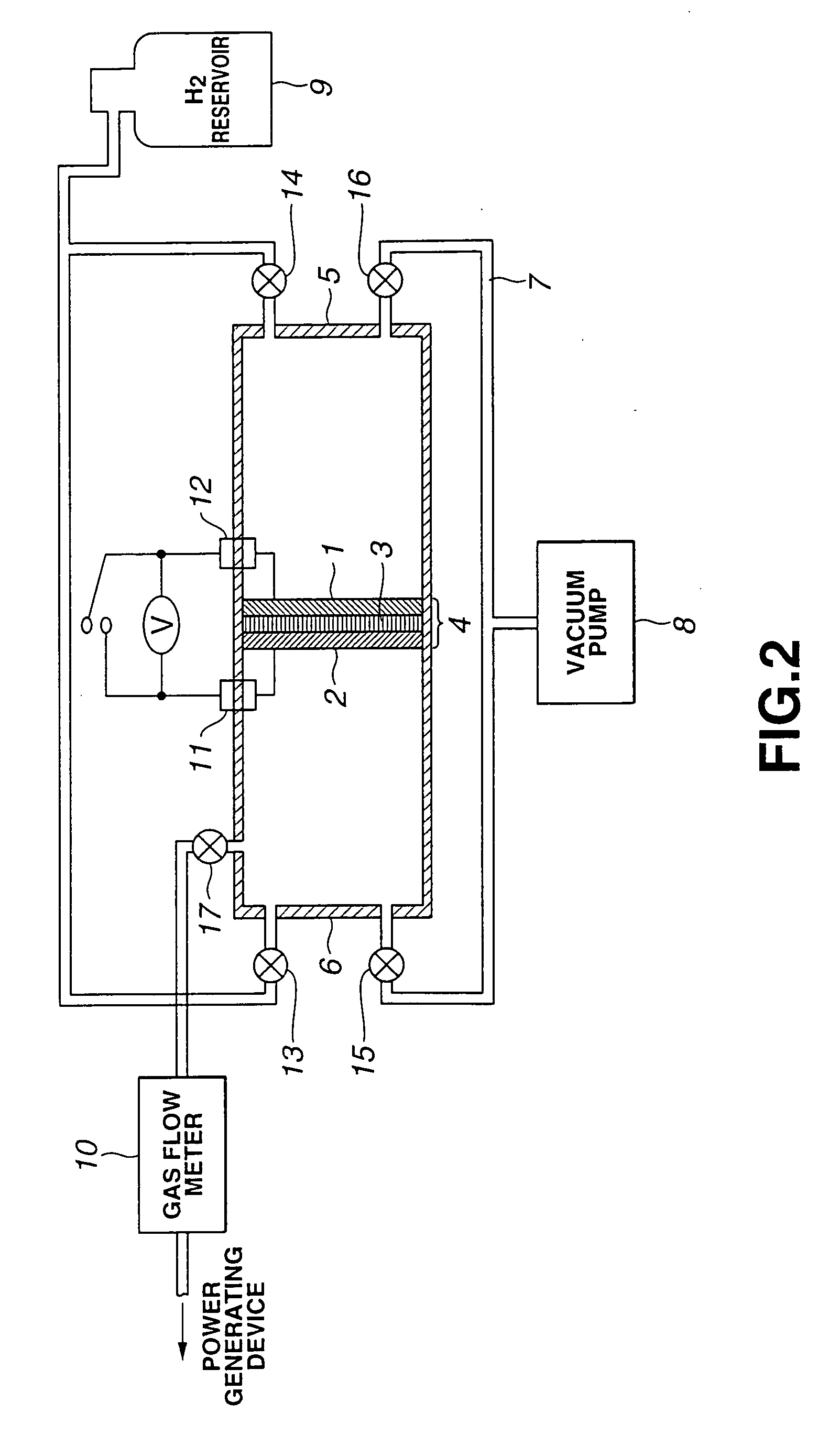
[0056] A pressure reducing device according to the present invention comprises, as shown in FIG. 2, an electrochemical cell 4 as a partition wall, having first and second catalytic electrodes 1 and 2 respectively forming first and second electrodes on which catalysts such as platinum are carried and a proton conductor 3 sandwiched in between the catalytic electrodes 1 and 2, and a high pressure vessel 5 and a low pressure vessel 6 disposed at both the sides of the electrochemical cell 4. A vacuum pump 8 is connected to the high pressure vessel 5 and the low pressure vessel 6 through a vacuum line 7. Further, an H2 reservoir 9 and a gas flow meter 10 are connected to the high pressure vessel 5 and the low pressure vessel 6. To each of the vessels 5 and 6, lead introducing terminals 11 and 12 are connected. To the end of the gas flow meter 10, a power generation device using hydrogen gas a...


PUM

PropertyMeasurementUnit
Pressureaaaaaaaaaa
Flow rateaaaaaaaaaa
Energyaaaaaaaaaa

Abstract

The present invention relates to a gas pressure regulator including an electrochemical cell (4) having a first electrode (1) for decomposing gas into ions, a second electrode (2) for converting the ions generated in the first electrode (1) into the gas again and an ion conductor (3) sandwiched in between both the electrodes (1) and (2); and a high pressure vessel (5) disposed in one side of the electrochemical cell (4). In this device, the gas is decomposed into the ions in the first electrode (1). The decomposed ions are allowed to pass through the ion conductor (3) sandwiched in between the first electrode (1) and the second electrode (2) and conducted to the second electrode (2) side. The conducted ions are reconverted into the gas in the second electrode (2).

Description

TECHNICAL FIELD [0001] The present invention relates to a pressure reducing device, an electrochemical device, a pressure reducing and pressurizing device, a gas storage device, a gas storage assist system, and a method for driving these devices. [0002] This application claims a priority on the basis of Japanese Patent Application No. 2002-009456 filed on Jan. 18, 2002 and Japanese Patent Application No. 2002-373798 filed on Dec. 25, 2002, the entireties of which are incorporated by reference herein. BACKGROUND ART [0003] As means for converting high pressure gas into low pressure gas, a mechanical gas regulator has been hitherto widely employed. The usual gas regulator has been a mechanical device as disclosed in, for instance, Japanese Patent Application Laid-Open No. H04-244506. [0004] Now, according to the contents described in the Japanese Patent Application Laid-Open No. H04-244506, the usual gas regulator will be described below. [0005] The usual gas regulator is formed as sh...

Claims


Application Information

Patent Timeline
IPC IPC(8): F23N1/00B01D53/32B01J19/00G05D16/20H01M8/04
CPCB01D53/326H01M8/04089Y02E60/50H01M8/04216H01M8/04126B01D53/32B01J19/00H01M8/04
Inventor WACHI, SHIGEAKIMARUYAMA, RYUICHIROATA, MASAFUMI
Owner SONY CORP
Why Eureka
Try Eureka