
Method And Apparatus For Determining The New Sample Points Of The Location Determination System In A Wireless Environment

Active Publication Date: 2008-07-03
IND TECH RES INST
View PDF2 Cites 9 Cited by
  • Summary
  • Abstract
  • Description
  • Claims
  • Application Information

AI Technical Summary

Benefits of technology

[0016]The present invention does not rely on the decision rules, and does not have problems caused by the wrong choice of decision rules. The present invention also provides the penalty mechanism of the error prediction of moving from one location to another location, and can solve the problem caused by the double-role attribute of the sample points on the border lines.

Problems solved by technology

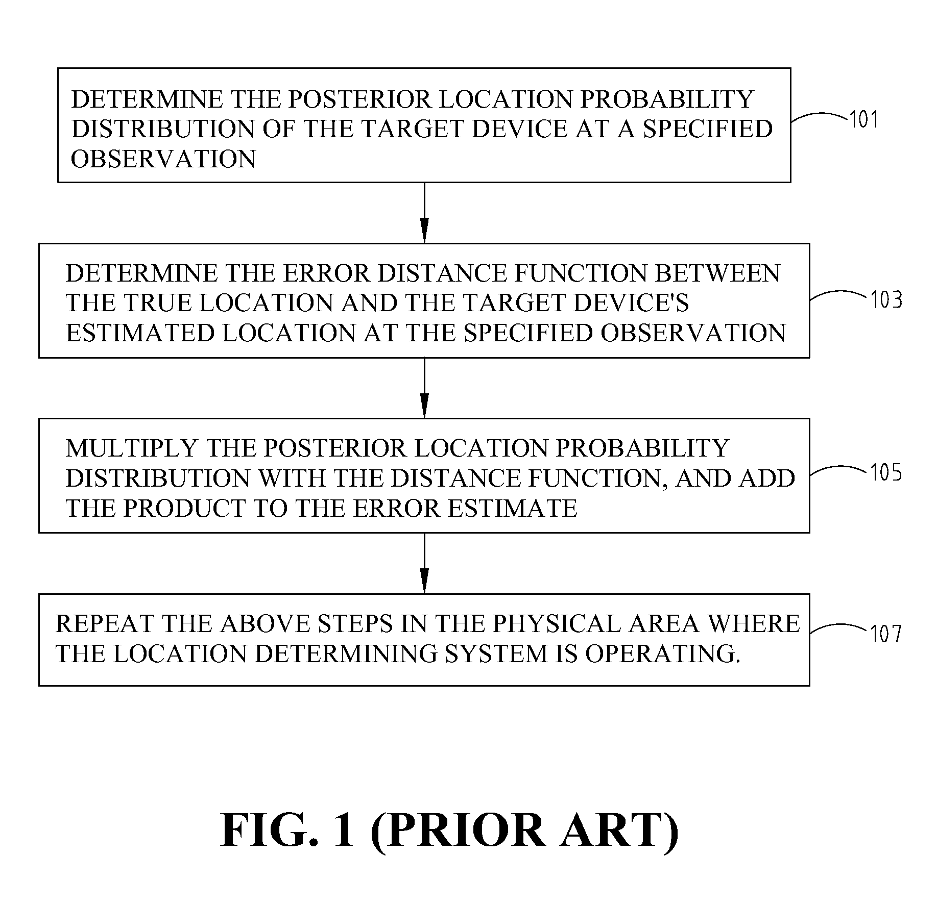
However, most environments usually use a large amount of sample points; therefore, it is impractical to collect the radio data.
Therefore, it is difficult for the error distance estimation to give good, objective, or effective suggestions on the new sample points, unless the optimal decision rule is taken into account.
However, if the random mapping decision rule is used, it is not suitable to use the error distance expectation to differentiate the location based on the received signals because the expectation is independent of the selection of sample points based on the observed radio signals.
Furthermore, when location determining models in different environments are taken into account, the grid size of the sample points of different models used in location estimation can be inconsistent.
However, if the location determining effect is not good after the training phase, new sample points must be added or calibrated.

Method used


Image

  • Method And Apparatus For Determining The New Sample Points Of The Location Determination System In A Wireless Environment
  • Method And Apparatus For Determining The New Sample Points Of The Location Determination System In A Wireless Environment
  • Method And Apparatus For Determining The New Sample Points Of The Location Determination System In A Wireless Environment

Examples


Embodiment Construction

[0027]The present invention is to determine the new sample points of a target device during the training phase of a wireless location determination system. The location determining technique is to use the radio signal observation at a location of the target device as a basis. The observations at a location reported by the target device form a probability distribution, which is a conditional probability. In other words, the conditional probability P(ot=mt|qt=st) means the probability that the target device reports the observation mt at location st, and qt and ot are respectively the location and observation variables of the target device at time t.

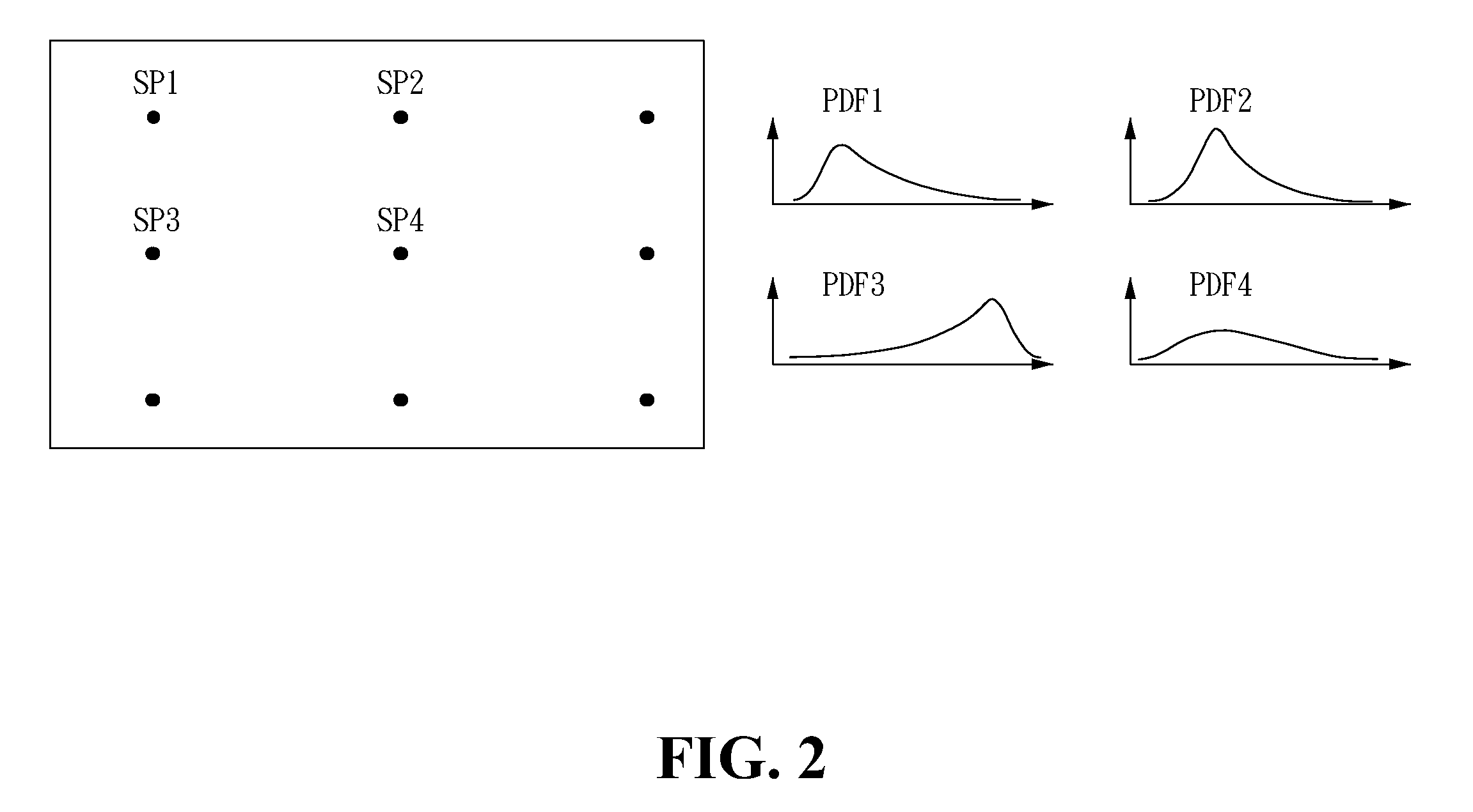
[0028]The probability distributions corresponding to the radio signals at different locations are independent with each other. As shown in FIG. 2, the four probability distributions PDF1-PDF4, corresponding to the radio signal received at four different locations, such as four sample points SP1-SP4, are independent. In general, there are si...


PUM


Abstract

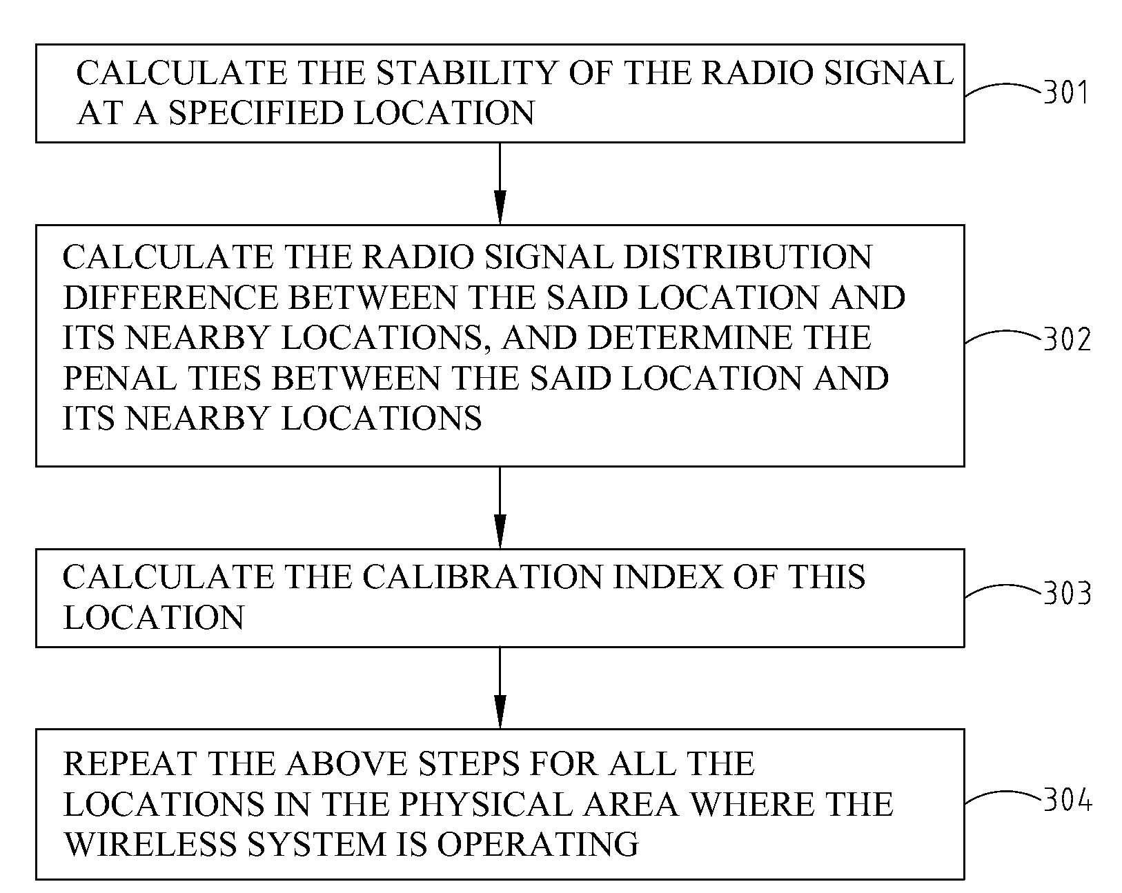
Disclosed is a method and apparatus for determining the new sample points of the location determination system in a wireless environment. In the training phase, after knowing the distribution of the observed radio signal of a location for a target device, the uncertainty of the probability distribution of the received radio signal is analyzed by a location probability distribution model. The radio signal distribution differences are calculated, and the penalties between the location in question and its nearby locations are also calculated, thereby determining whether a location is the candidate of new sample points or the recalibration points. This invention has nothing to do with decision rules and will not undergo the problems of choosing inappropriate decision rules. It also provides a penalty model for generating penalty of error prediction from one location to another location, which can as well easily mitigate the problem on the sample points with the double-role attribute of the border line.

Description

FIELD OF THE INVENTION[0001]The present invention generally relates to a method for determining the new sample points of a location determination system in a wireless environment.BACKGROUND OF THE INVENTION[0002]To estimate the location of a target device, a location determination system must estimate a quantity. The quantity must be at least a function of distance. The quantity can be the strength of the signal from the access point (AP). The signal strength will logarithmically decay in accordance with the distance in a free space. The location determination technique is based on the observation of the received radio signal at the target device. In general, the observations at a location form a probabilistic model. The probabilistic model describes the distribution of the received radio signal.[0003]The distribution of the observation at each sample point (SP) usually approximates the radio signals in the nearby regions. To establish the probabilistic model of each SP, it is neces...

Claims


Application Information

Patent Timeline
IPC IPC(8): G06F19/00
CPCG01S5/0252G01S5/02525
Inventor HSYU, MING-CHUTSUEI, WENCHEN, CHAO-NAN
Owner IND TECH RES INST
Learn More