
Magnetic toner

Active Publication Date: 2016-02-11
CANON KK
View PDF4 Cites 10 Cited by
  • Summary
  • Abstract
  • Description
  • Claims
  • Application Information

AI Technical Summary

Benefits of technology

The present invention relates to a magnetic toner that is designed for high-speed printing. The goal is to create a toner that can withstand longer periods of use and is easy to fuse at low temperatures. Additionally, the toner should prevent printed paper from sticking to surfaces.

Problems solved by technology

However, when it is assumed that the copying machine, the printer, or the like has a higher speed and a longer lifetime in the future, it is expected that an external stress such as stirring in its developing unit or an increase in temperature of its main body further strengthens, and hence a reduction in developability, an image defect, or melt adhesion to members occurs owing to the embedding of the external additive.
Accordingly, the toner is susceptible to improvement.
However, the addition of those spacer particles is expected to adversely affect the low-temperature fixability of the toner.
Accordingly, when a quantity of heat by which the temperature of the external additive can be sufficiently increased is charged into a fixing unit, there is a risk in that the temperature of a toner image after fixation hardly reduces, and hence the phenomenon in which upon lamination of sheets of paper immediately after printing, the sheets of paper adhere to each other, i.e., the so-called adhesion of printed paper occurs.
At present, however, there are an extremely large number of technological problems to be solved for such purpose, and the related-art toner is susceptible to improvement.

Method used


Image

  • Magnetic toner
  • Magnetic toner
  • Magnetic toner

Examples


production example 1

Releasing Agent Production Example 1

[0246]120 Parts of benzene, 100 parts of behenic acid, 80 parts of behenyl alcohol, and 8.0 parts of p-toluenesulfonic acid are loaded into a four-necked flask reactor mounted with a Dimroth reflux condenser and a Dean-Stark water separator, and are sufficiently stirred and dissolved, followed by reflux for 5 hours. After that, the valve of the water separator is opened and removal by azeotropic distillation is performed. After the removal by azeotropic distillation, the residue is sufficiently washed with sodium hydrogen carbonate. After that, the washed product is dried and benzene is removed by distillation. The resultant product is recrystallized, and is then washed and purified to synthesize a releasing agent 1 shown in Table 5.

Releasing Agent Production Examples 2 to 4

[0247]Releasing agents 2 to 4 shown in Table 5 are obtained by changing the kinds and amounts of the fatty acid and alcohol serving as raw materials in Releasing Agent Producti...

example 1

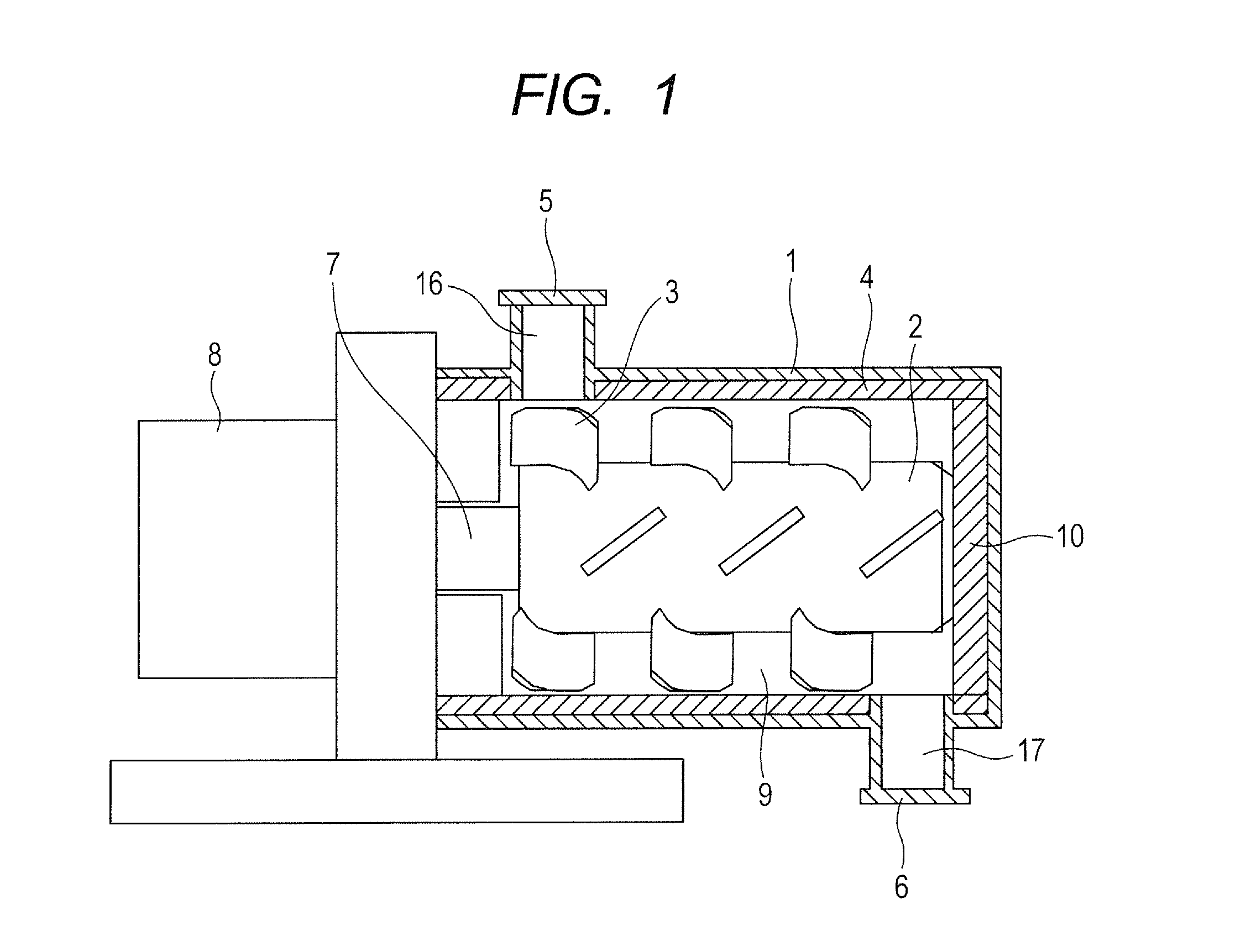
[0260]The magnetic toner particles 1 obtained in Magnetic Toner Particle Production Example 1 are subjected to an external addition and mixing treatment with an apparatus illustrated in FIG. 1.

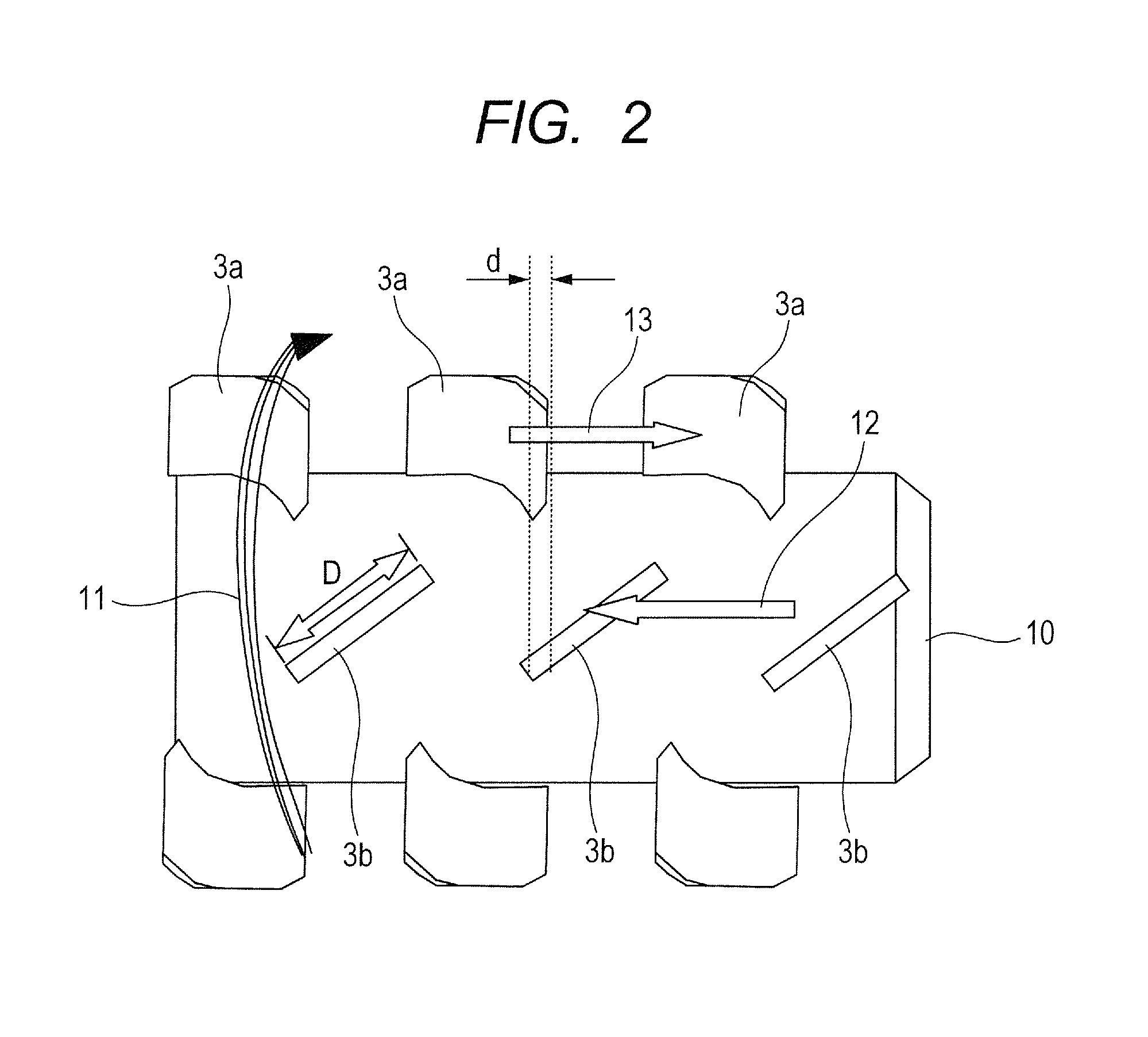
[0261]In this example, the apparatus illustrated in FIG. 1 in which the diameter of the inner peripheral portion of a main body casing 1 is 130 mm and the volume of a treatment space 9 is 2.0×10⁻³ m3 is used, the rated power of a driving portion 8 is set to 5.5 kW, and stirring members 3 are shaped as illustrated in FIG. 2. In addition, an overlapping width d between a stirring member 3a and a stirring member 3b in FIG. 2 is set to 0.25D with respect to a maximum width D of each of the stirring members 3, and a clearance between each of the stirring members 3 and the inner periphery of the main body casing 1 is set to 3.0 mm.

[0262]100 Parts of the magnetic toner particles 1, and additives shown in Tables 1 and 2 whose kinds and addition amounts were shown in Table 7 were loaded into the appara...

examples 2 to 13

[0282]Magnetic toners 2 to 13 are produced in the same manner as in Example 1 according to formulations shown in Table 7. The physical property values of the magnetic toners thus obtained are shown in Table 8, and results obtained by subjecting the toners to the same tests are shown in Table 9.


PUM


Abstract

Provided is a toner having good endurance stability and good low-temperature fixability in high-speed printing, and having good resistance to the adhesion of printed paper. The toner is a magnetic toner having, on the surface of toner particle containing a binder resin and an ester compound as a releasing agent, inorganic fine particle “a” and organic-inorganic composite fine particle having a volumetric specific heat of from 2,900 kJ / (m3·° C.) to 4,200 kJ / (m3·° C.), in which a coverage A of the surface of the toner particle with the inorganic fine particle “a” is 45.0% or more and 70.0% or less.

Description

BACKGROUND OF THE INVENTION[0001]1. Field of the Invention[0002]The present invention relates to a magnetic toner to be used in electrophotography, an image forming method for visualizing an electrostatic image, and a toner jet (hereinafter sometimes referred to simply as “toner”).[0003]2. Description of the Related Art[0004]In recent years, a copying machine, a printer, or the like has started to be required to have a higher speed and a longer lifetime, and hence a magnetic toner has started to need to be capable of standing longer use than a related-art one. Further, there has been a growing demand for the energy savings of an apparatus, and at the same time, excellent low-temperature fixing performance of the toner has been strongly required for corresponding to the demand.[0005]In general, the low-temperature fixing performance is related to the viscosity of the toner, and hence the property by virtue of which the toner quickly melts with heat at the time of fixation, i.e., the ...

Claims


Application Information

Patent Timeline
IPC IPC(8): G03G9/083
CPCG03G9/0839G03G9/083G03G9/08782G03G9/09716
Inventor TSUDA, SHOHEIHOTTA, YOJIRONISHIKAWA, KOJIFUJIMOTO, MASAMIYAMAZAKI, KATSUHISA
Owner CANON KK
Learn More