Ethernet-based data transmission method, ethernet nodes and control system

Inactive Publication Date: 2011-10-13
SUPCON GRP +1
View PDF6 Cites 9 Cited by
  • Summary
  • Abstract
  • Description
  • Claims
  • Application Information

AI Technical Summary

Benefits of technology

[0013]In the present disclosure, each of the nodes in the control system sends data in the time period for the node to send data, so that the problem of transmission collision caused by multiple nodes sending data at the sa

Problems solved by technology

However, if multiple nodes send data at the same time, then there may be transmission collision, so that some nodes or all the nodes desired for data transmission fail to send data.
However, it is discovered by the inventors upon studying the above solution that, when the node desired for data transmission retries the transmission after a period of time, there is still possibility for transmission collision,

Method used


Image

  • Ethernet-based data transmission method, ethernet nodes and control system
  • Ethernet-based data transmission method, ethernet nodes and control system
  • Ethernet-based data transmission method, ethernet nodes and control system

Examples


first preferred embodiment

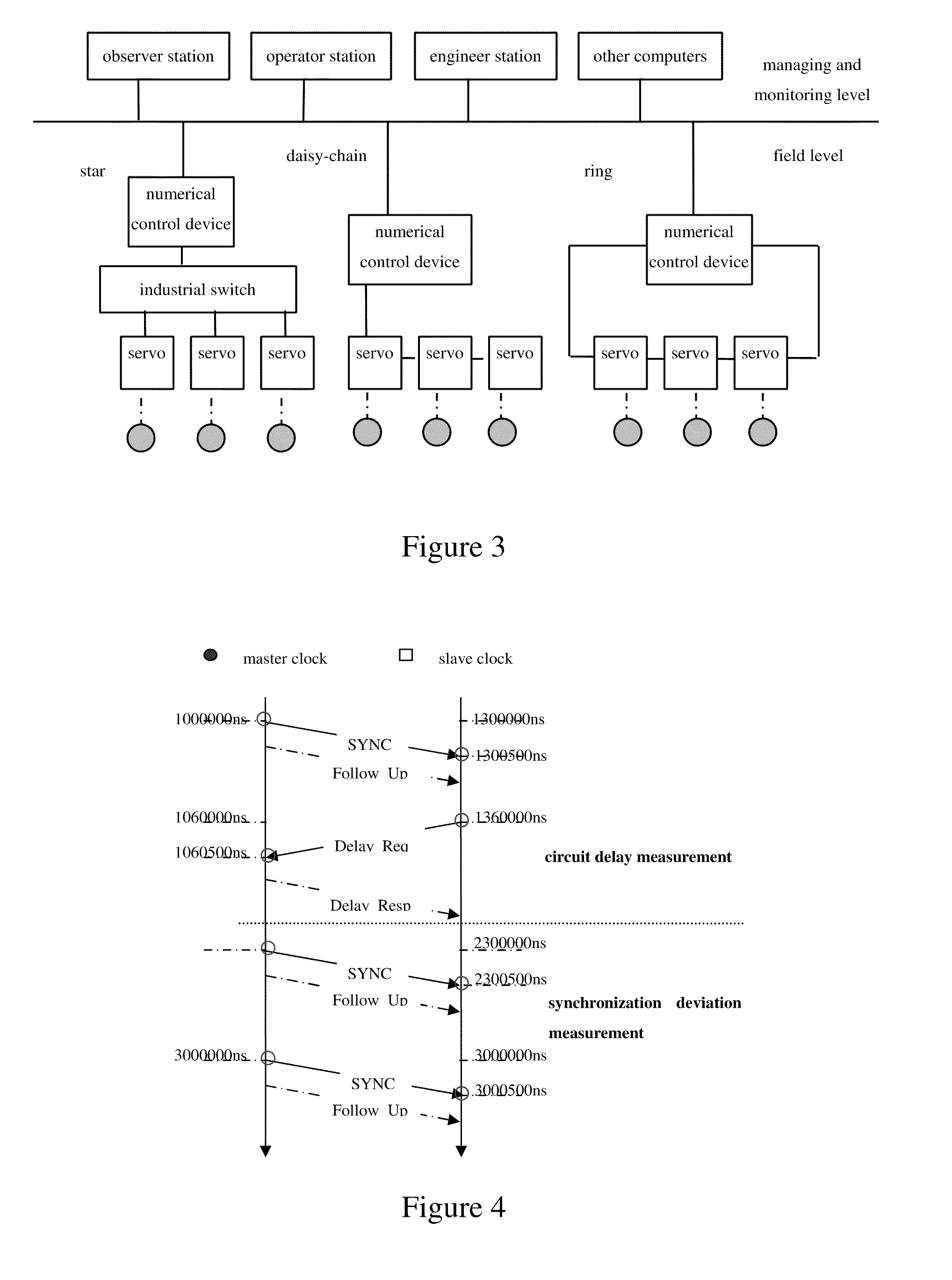
[0082]FIG. 3 shows a star topologic structure, a daisy-chain topologic structure, or a ring topologic structure of the Ethernet of the present disclosure. In the first preferred embodiment, the Ethernet is in a star topologic structure, as shown in FIG. 3, in which the local area network consists of one numerical control device, three servo drivers and one industrial switch.

[0083]As shown in FIG. 4, the clock is synchronized based on IEEE1588 Precision Clock Synchronization Protocol, and it is set that the numerical control device is the master clock (i.e. the clock source), the servo driver is the slave clock, and synchronization is performed between the master clock and the slave clock. After the numerical control system is powered, each servo driver measures the circuit delay between the numerical control device and the servo driver, and stores the delay. The circuit delay is measured by the following method:

[0084]The numerical control device sends a synchronization (SYNC) messag...

second preferred embodiment

[0122]The second preferred embodiment differs from the first preferred embodiment in that: in the second preferred embodiment, a daisy-chain topologic structure of the Ethernet is adopted, the clock synchronization is implemented by carrying the time stamp in the data to be sent, and the communication macro cycle does not include the random time period.

[0123]As shown in FIG. 11, the numerical control system includes one numerical control device and four servo drivers (referred to as servos in FIG. 11). The signal transmission delay on twisted-pair is 5.5 ns / m, and the delay caused by each device is 300 ns. The circuit delay between respective servo drivers and the numerical control device is the sum of the transmission delay caused by line and the delay caused by the devices. For example, the circuit delay Delayn between the servo driver 4 and the numerical control device is: 55 ns+300 ns+22 ns+300 ns+22 ns+300 ns+88 ns=1087 ns.

[0124]As shown in FIG. 12, the clock synchronization is...


PUM


Abstract

The invention provides an Ethernet-based data transmission method, which is applied to a control system with a plurality of nodes. The method comprises: a first node caches the data needed to be sent (S101); if the current communication macro-cycle comprises the time segment for the first node to send data, the first node sends the cached data in the time segment for the first node to send data within the current communication macro-cycle; if the current communication macro-cycle does not comprise the time segment for the first node to send data, the first node does not send the cached data in the current communication macro-cycle; wherein other nodes do not send data in the time segment for the first node to send data within the current communication macro-cycle, and the communication macro-cycles have same durations and each communication macro-cycle consists of a plurality of time segments with a fixed length (S102). The invention further provides Ethernet nodes and a control system.

Description

[0001]This application claims the benefit of priority to Chinese Patent Application No. 200910130848.5, entitled “ETHERNET-BASED DATA TRANSMISSION METHOD, ETHERNET NODES AND CONTROL SYSTEM”, filed on Apr. 15, 2009 with State Intellectual Property Office of PRC, the content of which is incorporated herein by reference in its entirety.FIELD OF THE INVENTION[0002]The present disclosure relates to the field of numerical control technique, and particularly relates to Ethernet-based data transmission technique.BACKGROUND OF THE INVENTION[0003]With the rapid development of Ethernet technique, Ethernet communication is widely used in more and more communication systems. Ethernet has the advantages of popular usage, mature technology and low cost, and the communication speed of Ethernet communication is obviously superior to that of other conventional serial communications.[0004]Presently, the Ethernet communication is used in some control systems, such as some numerical control systems. The...

Claims


Application Information

Patent Timeline
IPC IPC(8): G06F15/16
CPCH04L12/56H04J3/0667H04L49/351H04L12/417H04L12/28
Inventor FENG, DONGQINWANG, QIANGCHU, JIANJIN, JIANXIANG
Owner SUPCON GRP
Why Eureka
Try Eureka