Power consumption stabilization system & method

a power consumption stabilization and power consumption technology, applied in the field of digital logic circuits, can solve the problems of low power consumption, high power consumption, signal level change, etc., and achieve the effect of reducing the maximum power consumption, reducing peak power consumption, and reducing the design and layout of components

Inactive Publication Date: 2005-04-14
AGILENT TECH INC
View PDF8 Cites 41 Cited by
  • Summary
  • Abstract
  • Description
  • Claims
  • Application Information

AI Technical Summary

Benefits of technology

[0005] The present invention reduces the maximum power consumption for any digital circuit in which power consumption depends on data activity. Signals are scrambled and randomized before entering the digital circuit and unscrambled on exiting. Peak power consumption is reduced because the scrambled signal passing through the digital circuit is random. The scrambled signal will rarely be a continuing series of 10101010 transitions, which would consume the greatest amount of power. These improvements are achieved without limiting the design and layout of components or increasing integrated circuit complexity.

Problems solved by technology

There is low power consumption when signal levels are constant and high power consumption when the signal levels change often.
Power consumption in control circuits can also be subject to peaking power consumption.
For example, if an address counter has a large load, it will have high power consumption at certain control code changes such as from an all 1 code to an all 0 code.
This increases chip size, complexity, and cost.
Such measures for mitigating power consumption can limit the design and layout of components in integrated circuits as well as increasing integrated circuit complexity.

Method used


Image

  • Power consumption stabilization system & method
  • Power consumption stabilization system & method
  • Power consumption stabilization system & method

Examples


Embodiment Construction

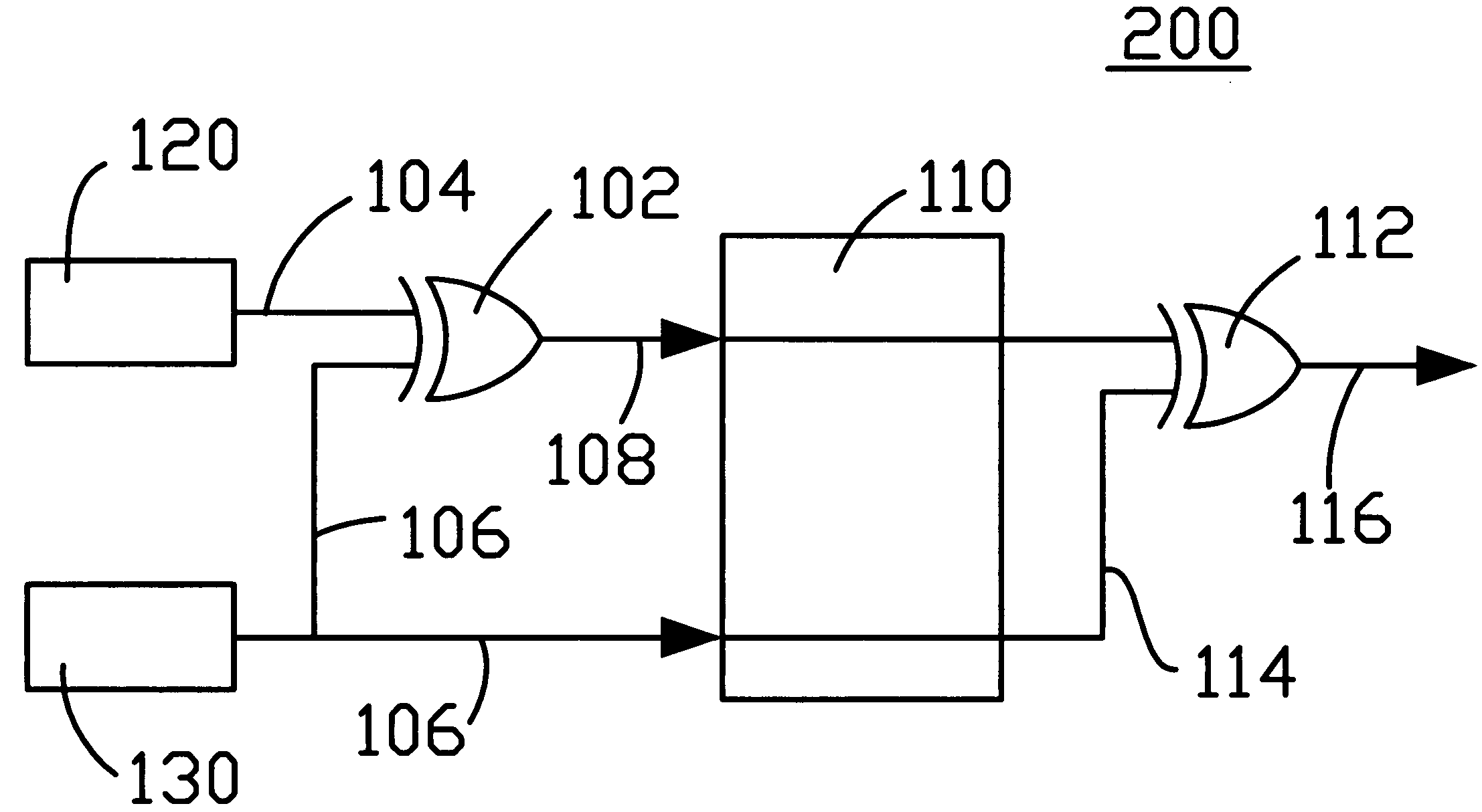
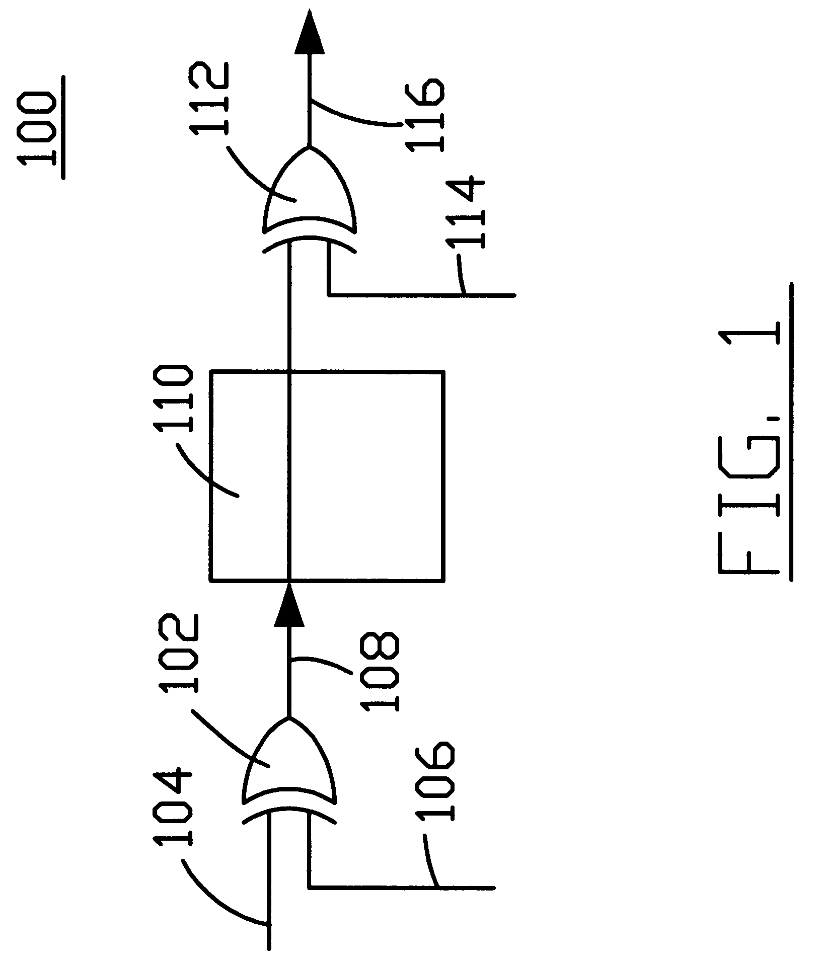
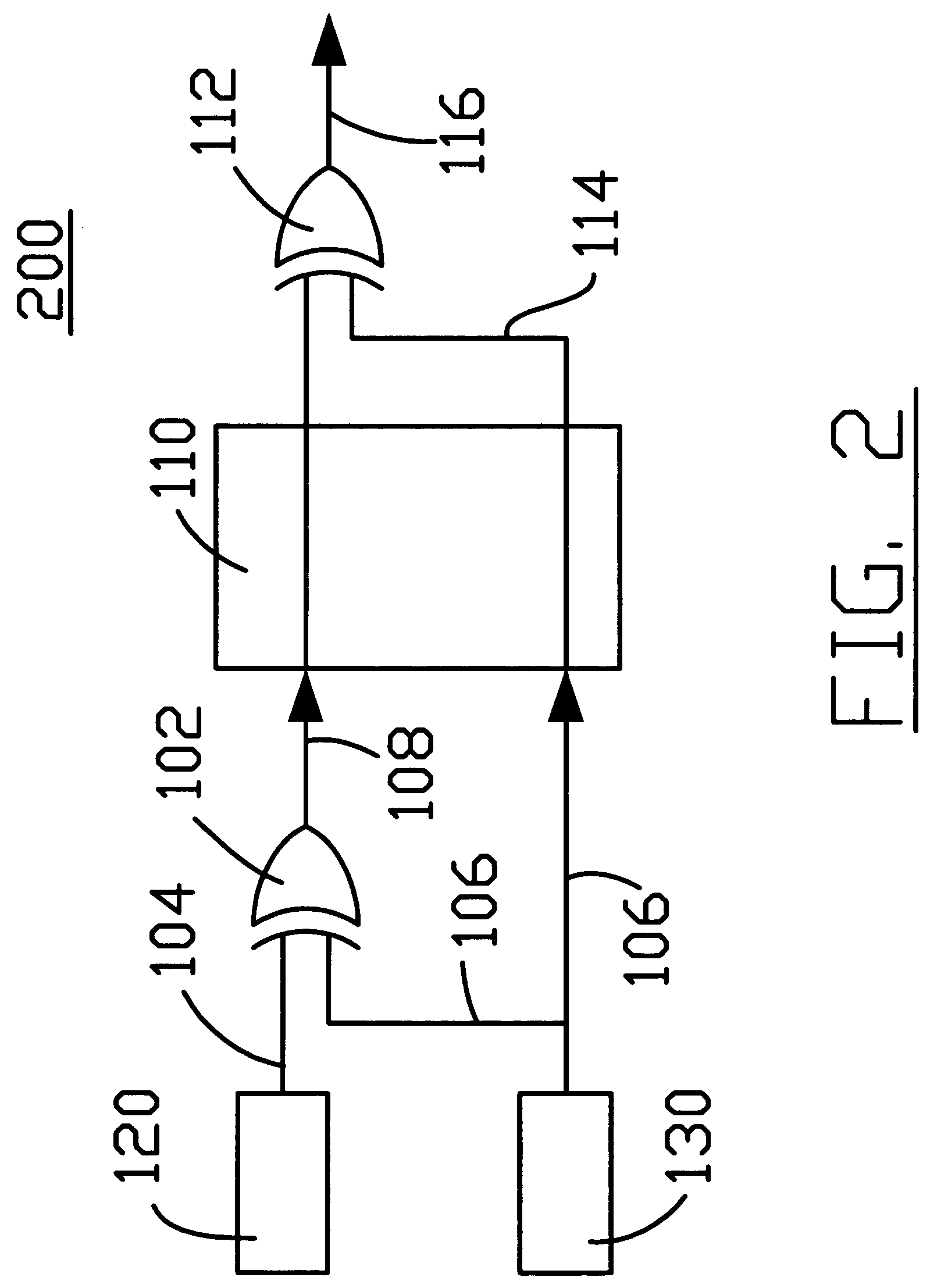
[0011]FIGS. 1-4 show block diagrams for power consumption stabilization systems for digital logic circuits. Generally, a first exclusive OR (XOR) gate receives a source signal and a scrambling random signal, and generates a scrambled signal. The scrambled signal is transmitted through a digital logic circuit, which has power consumption dependent on the number of transitions in a signal. The peak power consumption in the digital logic circuit is reduced because the scrambled signal has been randomized, so that the scrambled signal will rarely contain lengthy strings of alternating bits. For example, the scrambled signal is typically a random string such as 01110100, instead of a string of alternating ones and zeroes, such as 01010101. After the digital logic circuit, a second XOR gate receives the scrambled signal and a descrambling random signal, and generates unscrambled data. The descrambling random signal is logically identical to and has the same bit sequence as the scrambling ...


PUM


Abstract

A source signal is provided. The source signal is XORed with a scrambling random signal to generate a scrambled signal. The scrambled signal is transmitted through the digital logic circuit. The scrambled signal is XORed with the descrambling random signal logically identical to the scrambling random signal to produce a descrambled signal identical to the source signal. In one embodiment, the scrambling random signal is transmitted through the digital logic circuit and used as the descrambling random signal. In another embodiment, the scrambling random signal and descrambling random signal are generated independently using pseudo-random number generators. In yet another embodiment, the scrambling random signal is self-synchronizing and is contained within the pattern of the scrambled signal.

Description

TECHNICAL FIELD [0001] The technical field of this disclosure is digital logic circuits, particularly digital logic circuits having a power consumption stabilization system and methods of stabilizing power consumption. BACKGROUND OF THE INVENTION [0002] Power consumption in many digital logic circuits is a function of the number of signal level changes occurring in the circuit. There is low power consumption when signal levels are constant and high power consumption when the signal levels change often. For example, transmitting the sequence 10101010 requires twice the power of 10001000 and four times the power of 00001000 for a circuit where the power consumption is dependent on the frequency of transition. [0003] In large digital chips, logic circuits may be classified as control or data flow circuits. Control circuits determine where data goes or what operation will occur. Data flow circuits handle the actual information being processed, such as implementing arithmetic operations....

Claims


Application Information

Patent Timeline
Patent Type & Authority Applications(United States)
IPC IPC(8): H03K17/16H03M7/00H04L25/03H04L25/49
CPCH04L25/4906H04L25/03866
Inventor NEFF, ROBERT M. R.
Owner AGILENT TECH INC
Why Eureka
Try Eureka