Differential pipelined analog to digital converter with successive approximation register subconverter stages

a digital converter and subconverter technology, applied in the field of signal processing, can solve the problems of consuming a relatively large amount of power, flash converters require a large number of comparator circuits, and important design considerations, and achieve the effects of reducing the gain factor, facilitating the improvement of system bandwidth, and increasing the gain factor

Inactive Publication Date: 2005-04-14
TEXAS INSTR INC
View PDF14 Cites 51 Cited by
  • Summary
  • Abstract
  • Description
  • Claims
  • Application Information

AI Technical Summary

Benefits of technology

The invention relates to analog to digital conversion systems (A / D converters or ADCs) in which two or more multi-bit successive approximation register (SAR) subconverter stages are cascaded to form a pipelined conversion system receiving an analog input and providing a digital output. The cascaded SAR stages include capacitor arrays and switching systems to selectively couple the capacitors to array inputs, array outputs, or reference voltages for operation in sample, conversion, and residue amplification modes. The use of pipelined multi-bit SAR stages provides the advantages of high conversion speed and low power consumption, along with reduced die area compared with conventional pipelined flash converters and non-pipelined designs. In one implementation, the SAR subconverter stages are fully differential, wherein the capacitors are switched according to a thermometer code to also reduce converter differential non-linearity (DNL), and the first subconverter stage gain is reduced to improve the conversion system bandwidth.
In another aspect of the invention, the first digital output signal comprises J bits, where J is an integer greater than 1, wherein the first stage has a residue output gain factor less than 2(J-1). Conventional pipelined converters, such as that of FIGS. 1A-1C, provide a first stage gain of 2(J-1), wherein the first stage's bandwidth limits the conversion speed of the entire conversion system. The inventor has appreciated that reducing the gain factor for the first SAR stage (e.g., below 2(J-1)) facilitates improved system bandwidth, wherein the second stage can be made with an increased gain factor to compensate for the reduced range in the first residue output signal. For example, where the second stage digital output comprises K bits (e.g., K being an integer greater than 1), the second subconverter stage gain factor is made to be greater than 2(K-1) in one implementation of the invention.
In yet another aspect of the invention, the subconverter stage capacitors have substantially equal capacitance values (e.g., not binary weighted), wherein the switching systems selectively couple the individual capacitors according to an intermediate digital signal in a thermometer code. The inventor has found that switching a capacitor array using thermometer coding reduces differential non-linearity (DNL) compared with systems that switch capacitors of different sizes (e.g., values) in and out in changing between digital values. The use of thermometer coding in the SAR subconverter stage intermediate digital signals ensures that only one capacitance value is being changed in a transition from one code to the next, wherein system DNL is reduced in comparison with conventional binary coding techniques.

Problems solved by technology

At the same time, however, power consumption is an important design consideration, wherein portable devices need to perform high-resolution analog to digital conversions while consuming a minimal amount of power.
However, flash converters require a large number of comparator circuits.
As a result, flash type converters occupy a large amount of area in an integrated circuit, and also consume a relatively high amount of power.
However, these conventional pipelined flash converter systems 10 still occupy a relatively large amount of die area, due at least in part to the provision of 2M comparator circuits 52 in each stage 12, and the system 10 consumes a considerable amount of power.

Method used


Image

  • Differential pipelined analog to digital converter with successive approximation register subconverter stages
  • Differential pipelined analog to digital converter with successive approximation register subconverter stages
  • Differential pipelined analog to digital converter with successive approximation register subconverter stages

Examples


Embodiment Construction

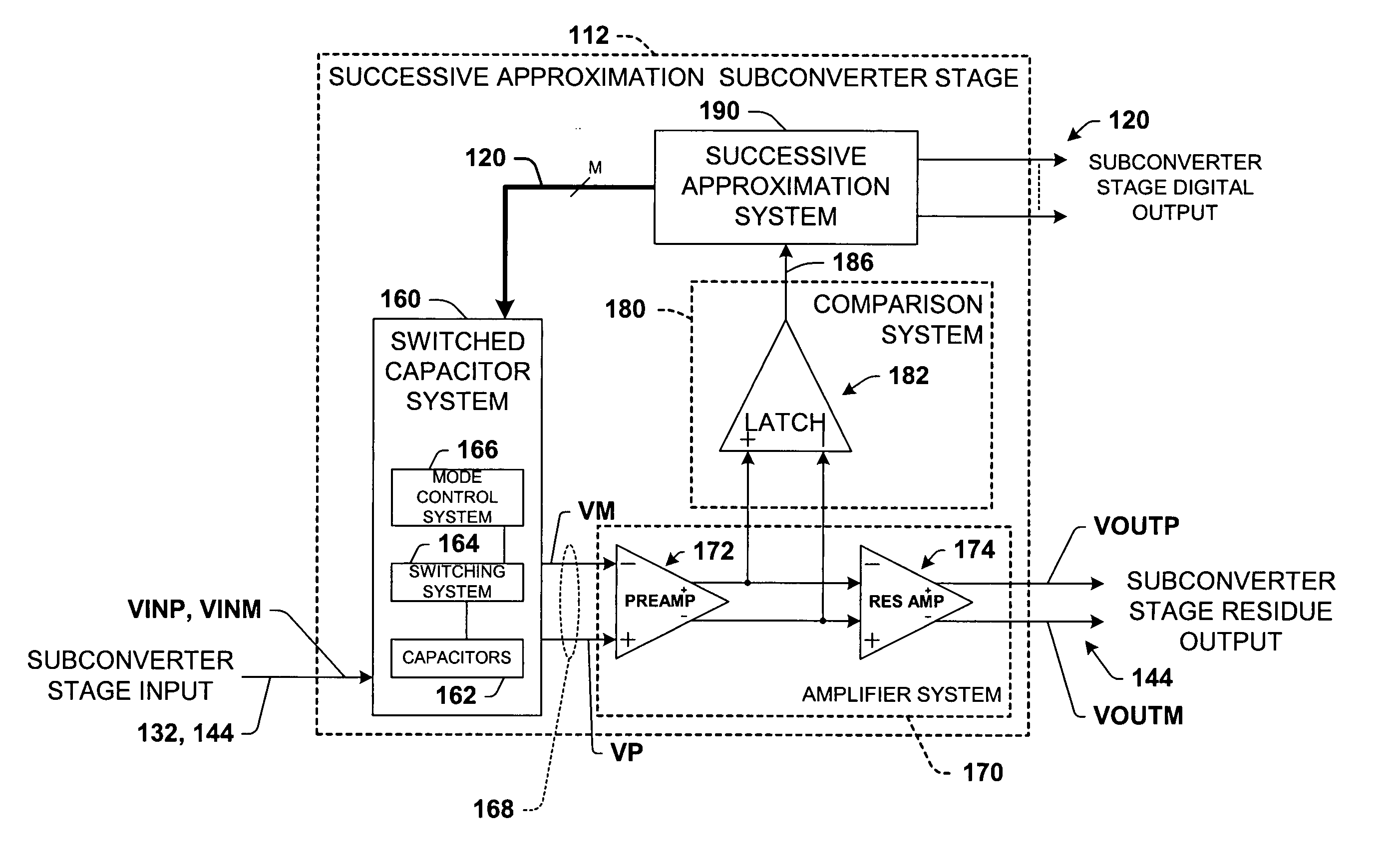
One or more exemplary implementations of the present invention will now be described with reference to the attached drawings, wherein like reference numerals are used to refer to like elements throughout. The invention relates to pipelined analog to digital conversion systems with cascaded multi-bit SAR subconverter stages that provide a digital output representative of a system analog input. Several exemplary fully differential A / D converters are illustrated and described hereinafter, wherein the various aspects of the invention may also be employed in conjunction with single-ended conversion systems.

Referring initially to FIGS. 2A-2F, an exemplary pipelined A / D conversion system 110 is illustrated, having a plurality of cascaded subconverter stages 112, including a first subconverter stage 112a receiving an analog input 132. A digital correction unit 118 provides conversion control signals 116 to the subconverter stages 112 and receives a digital output 120 from each of the sta...


PUM


Abstract

Pipelined analog to digital conversion systems are provided having cascaded multi-bit successive approximation register subconverter stages. Capacitor arrays are provided in the subconverter stages, where switching logic selectively couples the capacitors to operate in sample, conversion, and residue amplification modes for generating multi-bit subconverter digital outputs and analog subconverter residue outputs. In one implementation, the capacitors are switched according to a thermometer code to reduce differential converter non-linearity, and the first subconverter stage gain is reduced to improve the conversion system bandwidth.

Description

FIELD OF INVENTION The present invention relates generally to signal processing, and more particularly to a pipeline analog to digital data converter having pipelined fully differential multi-bit successive approximation register subconverter stages. BACKGROUND OF THE INVENTION Wireless communications products and other modern electronic devices typically process and generate both digital and analog signals. To perform their intended functions, these systems often convert analog signals into digital signals, referred to as analog to digital (A / D) conversion. Accordingly, these systems require circuitry to interface signals from the analog domain to signals in the digital domain so that they may perform further digital signal processing. In particular, analog to digital conversion systems (A / D converters, or ADCs) are needed to interface the analog and digital domains. Advances in wireless communications devices, DVD systems, and other related technologies indicate a need for incr...

Claims


Application Information

Patent Timeline
Patent Type & Authority Applications(United States)
IPC IPC(8): H03M1/06H03M1/12H03M1/14H03M1/16H03M1/34H03M1/46H03M1/80
CPCH03M1/0695H03M1/164H03M1/806H03M1/804H03M1/46
Inventor CAI, QI
Owner TEXAS INSTR INC
Why Eureka
Try Eureka