Digital/analog converter, display driver and display

a digital converter and display driver technology, applied in bridges, code conversion, instruments, etc., can solve the problems of increasing the power consumption of the dac, and the power consumption of the buffer, so as to achieve low power consumption, reduce power consumption, and reduce power consumption.

Inactive Publication Date: 2005-08-04
SHARP KK
View PDF9 Cites 11 Cited by
  • Summary
  • Abstract
  • Description
  • Claims
  • Application Information

AI Technical Summary

Benefits of technology

[0024] It is thus possible to provide a converter which does not require a buffer and hence is of lower power consumption. The transfer function of the converter may be linear or non-linear and only two reference voltages are required. These reference voltages may be at the limits of the required output range and are simple to generate with relatively low power consumption. The converter does not have to “dominate” the size of a capacitive load so that integration area can be reduced, power consumption can be reduced and speed of conversion can be increased.

Problems solved by technology

However, such buffers are a substantial source of power consumption.
However, this increases the power consumption of and the area of an integrated circuit occupied by the DAC.
However, this also increases the power consumption of the DAC and may also require more complex or powerful circuitry to generate the higher reference voltage.
However, the same limit on the maximum output voltage as described hereinbefore applies to such an arrangement.
Further, such a DAC is restricted to providing transfer characteristics with rotational symmetry.
Thus, although a DAC of this type can approximate the curve illustrated in FIG. 2, in general it cannot adequately approximate non-symmetrical curves such as that illustrated in FIG. 3.

Method used


Image

  • Digital/analog converter, display driver and display
  • Digital/analog converter, display driver and display
  • Digital/analog converter, display driver and display

Examples


Embodiment Construction

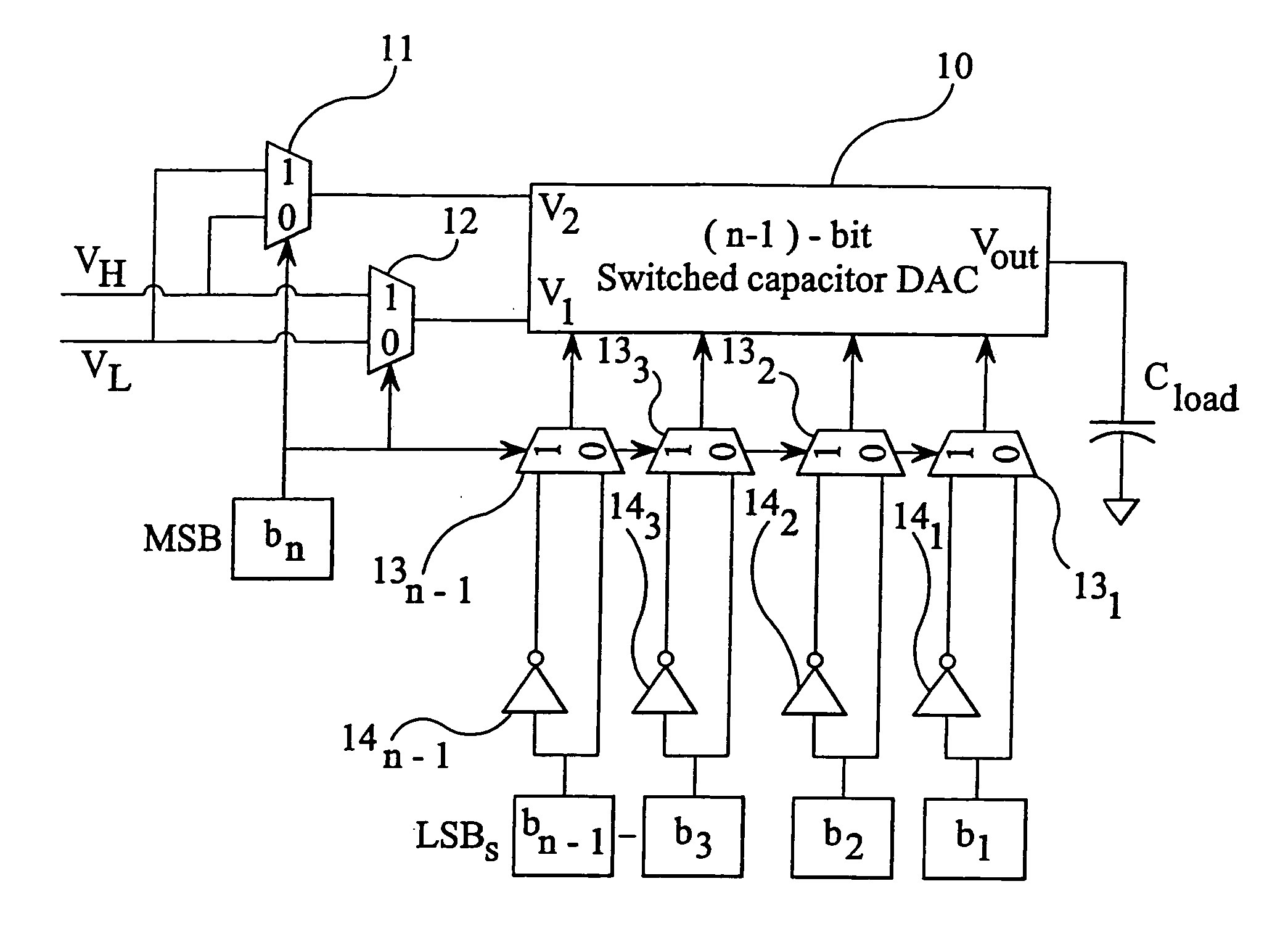
[0039] The DAC shown in FIG. 9 converts n-bit input words or codes to an output voltage range between and including a lower reference voltage VL and a higher reference voltage VH. The DAC comprises an (n-1) bit switched capacitor DAC 10 of the bufferless type with an output VOUT connected directly to a capacitive load CLOAD, for example comprising a data line of an active matrix liquid crystal device. The DAC 10 has reference voltage inputs V1 and V2 connected to the outputs of 2-input multiplexers 11 and 12 acting as electronic changeover switches controlled by the most significant bit (MSB) b. First inputs of the multiplexers 11 and 12 are connected to receive the reference voltages VL and VH, respectively, whereas second inputs thereof are connected to receive the reference voltages VH and VL, respectively. When the value of the most significant bit b, is 0, the inputs V1 and V2 are connected by the multiplexers to receive the reference voltages VL and VH. Conversely, when the mo...


PUM

PropertyMeasurementUnit
reference voltageaaaaaaaaaa
reference voltagesaaaaaaaaaa
power consumptionaaaaaaaaaa

Abstract

An n-bit digital / analog converter is provided for converting an n-bit digital word to a corresponding voltage. The converter comprises an (n-1) bit bufferless switched capacitor digital / analog converter (10) having an output (Vout) for direct connection to a capacitive load (CLOAD). The (n-1) bit converter (10) also has first and second reference voltage inputs (V1, V2) and an (n-1) bit digital input. An (n-1) bit selective inverter (131, . . . , 13n-1, 141, . . . , 14n-1) supplies the (n-1) least significant bits to the digital input and inverts them if the most significant bit has a certain value. A switching arrangement (11, 12) connects the first and second reference voltage inputs (V1, V2) to receive first and second or second and first reference voltages depending on the value of the most significant bit.

Description

FIELD OF THE INVENTION [0001] The present invention relates to a digital / analog converter, to a display driver including such a converter, and to a display including such a driver. Such a converter may be used, for example, for driving matrix columns of a liquid crystal display. A particular application of such a converter is in small display panels for portable applications where power consumption is at a premium. BACKGROUND OF THE INVENTION [0002]FIG. 1 of the accompanying drawings illustrates a known type of switched capacitor digital / analog converter (DAC) for converting an n-bit digital word to a corresponding analog output. The DAC comprises n-capacitors C1, . . . , Cn with the capacitance Ci of each ith capacitor being equal to 2(i-1) C1. The DAC further comprises a terminating capacitor CTERM connected between the input of a unity gain buffer 1 and ground. The first electrodes of the capacitors C1, . . . , Cn are connected together and to the first terminal of the terminatin...

Claims


Application Information

Patent Timeline
Patent Type & Authority Applications(United States)
IPC IPC(8): H03M1/66G02F1/133G06F15/00G09G3/36H03M1/70H03M1/74H03M1/80H03M1/84
CPCH03M1/804E01D19/045
Inventor ZEBEDEE, PATRICK
Owner SHARP KK
Why Eureka
Try Eureka