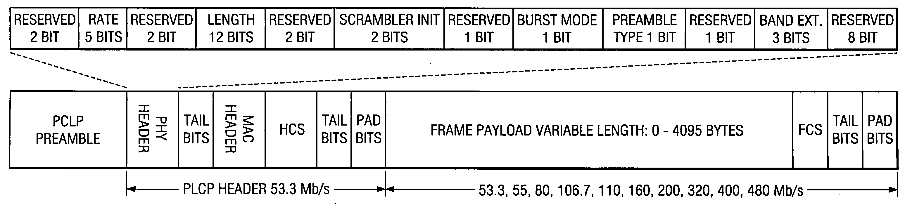
[0038] New PLCP Frame Format
[0039] In view of the above drawbacks in the prior art PLCP Frame Format discussed in the background, it is desirable to keep the PLCP preamble and PLCP header the same in both the 3-band and 7-band modes, thereby simplifying the state machine in the receiver. Additionally, the information indicating if the packet is in the 3-band mode or the 7-band mode can be embedded in the PLCP header, thereby improving the decoding performance of this information and reducing the packet errors.
[0040] A first modification made to the PLCP frame format is to keep the PLCP preamble and the PLCP header the same for both the 3-band mode and the 7-band mode. The advantage is that this simplifies the state machine for the receiver and ensure backwards compatibility with legacy devices.
[0041] A second new teaching according to one embodiment of the present invention is adding an extension bits field for various extensions of the MB-OFDM physical layer. These extension bits in the Header can be used to identify the features of the packet including band extension, for specifying data rates less than the current proposed 55 Mb/s and rates above 480 Mb/s and/or specifying information regarding possible different MIMO (Multiple Input Multiple Output) modes of the system or possible advanced coding schemes. For the case where the extension bits are for band extension these extension bits are added to keep the PLCP preamble and PLCP header the same for both a 3-band mode and a 7-band mode. In addition, the information that conveys whether the device should stay in the 3-band mode or switch to a 7-band mode (and expect additional channel estimation sequences) is now embedded into the header, where it can be more reliably decoded. A block diagram of the new PLCP frame format according to one embodiment of the present invention is shown in FIG. 7. This figure shows that there is a three bit field, called the extension field, which indicates whether the device should stay in a 3-band mode or switch to a 7-band mode. By allocating three bits, we are also allowing for future expansion into more bands, such as an 11-band mode. Also as mentioned previously the extension field can also be used to indicate low data rates and/or MIMO modes of the system and advanced coding schemes.
[0042] A consequence of embedding the band extension information into the PHY header is that the number of OFDM symbols describing the PLCP header has increased from 7 to 12. Note that an additional OFDM symbol only increases the overall PLCP header length by 312.5 ns. This additional time should not result in any significant change in throughput. A benefit of increasing the number of OFDM symbols in the PLCP header is that the number of reserved bits in the PHY header can now be increased. Having additional reserved bits will allow for a graceful expansion of the IEEE 802.15.3a standard. Additional information on the exact structure of the PHY header will be discussed later in this patent description.
[0043] An additional benefit of the new PLCP header consisting of 12 OFDM symbols is that it is more amenable to time-spreading and fits the structure of the interleaver. Time-spreading is an idea where information is spread in time by repeating the same information in two consecutive OFDM slots. Note that repeating the information does not imply that the same OFDM symbol is transmitted twice. It just means that the same information is contained in both OFDM symbols. One example could be that the second OFDM symbol is a time-reversed version of the first OFDM symbol. The current MB-OFDM proposal uses frequency-domain spreading, but it can also use time-domain spreading, or time-spreading.
[0044] An example of the proposed PLCP frame format in the time-domain for the 7-band mode is illustrated in FIG. 8. Channels 1-3 represent the three low band channels and the channels 4-7 represent the 4 high bands. The proposed preamble in FIG. 8 contains synchronization symbols and the channel estimation symbols for the lower three bands as in the current OFDM proposal presented in FIG. 2. In accordance with the present invention the entire PLCP header follows on the lower three bands followed by the band extension containing the channel estimation symbols for the upper bands (Channels 4-7) and we teach to decode the PHY header bits before we go to the other higher bands.
[0045] An additional modification that is made to the PLCP header is that an additional six (6) tail bits B are added after the PHY header A in FIG. 7. A block diagram of the new PLCP frame format according to one embodiment of the present invention is shown in FIG. 6. The advantage of adding these tail bits is to flush the memory of the convolutional decoder after receiving the PHY header and ensuring that the PHY header can be decoded separately from the MAC header. This makes it easier for the system to meet the latency requirements. Note that the latency is an important issue that is considered in this design, because the extension bits must be decoded in time in order to tell the radio to start tuning to the upper four frequencies. If these bits are not decoded on time, then the receiver will not be able to properly receive the additional channel estimation sequences and therefore, will not have the correct frequency-domain channel impulse response for the upper four bands.
[0046] New PHY Header
[0047] In view of the above issues discussed in the background under the PHY Header, it is desirable to increase the number of information bits in the PHY header including the reserved bits and also increase and make the number of OFDM symbols even and ensure that the header is aligned on the interleaver boundary.
[0048] A new proposed PHY header according to one embodiment of the present invention is shown in FIG. 9. This new header allows the transmitter to provide additional information data rates (5 bits instead of 3 bits) and also the transmitter to provide information to the receiver of any extensions including specifying using a 3-band more or a 7-band or a different band mode. The extension field can also be used for specifying data rates less than the current proposed 55 Mb/s and rates above 480 Mb/s and/or specifying information regarding possible MIMO (Multiple Input Multiple Output) modes of the system and advanced coding schemes.
[0049] Bits 0, 1, 7, 8, 21, 22, 25, 28, and 32-39 of the PHY header are reserved for future use. Bits 29-31 shall encode the EXTENSION field. Bits 2-6 shall encode the RATE. Bits 9-20 shall encode the LENGTH field, with the least significant bit (LSB) being transmitted first. Bits 23-24 shall encode the initial state of the scrambler, which is used to synchronize the descrambler of the receiver.
[0050] Depending on the information data rate (RATE), the bits R1-R5 shall be set according to the values in Table 1. TABLE 1 Rate-dependent parameters Rate (Mb/s R1-R5 53.3 00000 80 00001 106.7 00010 160 00011 200 00100 320 00101 400 00110 Reserved 01000-11111
[0051] The PLCP Length field shall be an unsigned 12-bit integer that indicates the number of octets in the frame payload (which does not include the FCS, the tail bits, or the pad bits). The bits S1-S2 shall be set according to the scrambler seed identifier value. This two-bit value corresponds to the seed value chosen for the data scrambler. The Extension field shall be set according to the values in Table 2. TABLE 2 Rate-dependent parameters Extension B1-B3 3-Band 000 7-Band 001 Reserved 010-111
[0052] There is also a Burst Mode bit (BM bit) and Preamble Type bit (PT bit). The BM bit (0=next packet is not part of the burst mode, 1=next packet is part of the burst mode) is used to indicate to the receiver the next packet will be part of the burst. This helps configure the hardware quickly in order to properly receive the next frame. In addition, the Preamble Type bit (0=long preamble, 1—short preamble) tells the receiver the type of preamble (short or long) that will be used in the next burst packet. This again is needed in order to quickly set up the hardware.
[0053] New Prefix
[0054] In view of the problems discussed in the background with the cyclic prefix it is desirable to remove the cyclic prefix and use a zero prefix which removes the structure in the OFDM symbol and the transmitted waveform.
[0055] It is proposed herein that a zero-padded prefix (ZPP) will work as well as a cyclic prefix in OFDM-based systems. See B. Muquet et al., “Cyclic Prefix or Zero Padding for Wireless Multicarrier Transmission?”, IEEE Transactions on Communications, vol. 50, no. 12, December 2002. A zero prefix corresponds to appending 32 zero samples before the output of the IFFT. See FIG. 10. The only modification at the receiver is to collect additional samples corresponding to the length of the prefix and to use an overlap-and-add method to restore the circular convolution property. The advantages of a zero prefix are as follows: [0056] 1) When zero-padded prefix (ZPP) is used, the structure in the transmitted signal is eliminated resulting in a flat power density plot as illustrated in FIG. 11. [0057] 2) The power consumption at the transmitter can be reduced because the power required to transmit a cyclic prefix is no longer needed. [0058] 3) In addition, a higher transmitter power can be used when there is a zero cyclic prefix. The reason for this is because the time span for the zero prefix can be incorporated into the pulse repetition interval (PRI). The additional time increase in the PRI will result in an additional 0.97 dB of transmit power. [0059] 4) Using a zero prefix instead of the cyclic prefix removes the structure in the OFDM symbol and the transmitted waveform. As a result, the ripples in the transmitted spectrum are non-existent. This means that the 1.3 dB back-off required in transmit power when using a cyclic prefix is no longer needed for the case when the system uses a zero prefix.
[0060] It is also proposed herein that a zero-padded postfix (ZPP) can be used with all the advantages that are seen with a zero-padded prefix. A zero-padded postfix corresponds to appending 32 zero samples after the output of the IFFT. See FIG. 14. The only modification at the receiver is to collect additional received samples corresponding to the length of the postfix and to use an overlap-and-add method to restore the circular convolution property. The advantages of a zero-padded postfix are similar to the advantages of a zero-padded prefix. The zero-prefix and/or zero-postfix can be of length 32 or 37. When we use 37, we eliminate the guard interval.
[0061] New Packet Synchronization Sequence
[0062] In view of the issue presented in the background of the invention, it is desirable to use a packet synchronization sequence that has no significant side-lobe characteristics. Removing the artificial side-lobes created due to the correlation could significantly help in packet detection.
[0063] It is proposed herein to use a length 160 hierarchical sequence instead of the cyclically extended 128 length hierarchical sequence. The advantage of a 160 length sequence is that there will not be any artificial side-lobes. In addition, the length of the two packets synchronization sequence is the same so that there will be not be changes in terms of the PRI rate.
[0064] The length 160 hierarchical sequences are created by spreading a length 16 bi-phase sequence with a length 10 bi-phase. These sequences are known to have the minimum peak side-lobes. A diagram showing how to create the length 160 hierarchical sequences is shown in FIG. 12.
[0065] Sequence A and B are enumerated in Table 3 and Table 4. TABLE 3 Sequence A Preamble Pattern Sequence A 1 −1 −1 1 −1 1 −1 −1 1 1 −1 −1 −1 −1 −1 1 1 2 −1 1 1 −1 1 −1 1 1 −1 −1 1 1 1 1 1 −1 3 −1 1 −1 −1 1 −1 −1 −1 1 −1 −1 −1 1 1 1 1 4 −1 1 1 −1 1 1 1 −1 1 1 1 −1 −1 −1 −1 1
[0066] TABLE 4 Sequence B Preamble Pattern Sequence B 1 1 −1 −1 1 −1 −1 −1 1 1 1 2 1 −1 −1 1 −1 −1 −1 1 1 1 3 1 1 1 −1 −1 −1 1 −1 −1 1 4 1 1 1 −1 −1 −1 1 −1 −1 1
[0067] The reason for sticking with a hierarchical sequence as the basis of the packet synchronization sequence is that there is an efficient implementation for the correlator. The correlator is typically used for packet detection at the receiver. Since the receiver will be in a listening mode (i.e. packet detection) for a significant portion of its operation, we need to use efficient algorithms that result in low power consumption.
[0068] In addition, we have also specified 4 different preambles. These preambles were chosen so as to minimize the peak cross-correlation. By choosing low cross-correlation properties, it will be easier for the devices to distinguish between the different piconets. Also, the individual sequences were chosen so that each sequence has good auto-correlation properties. The reason for choosing different preambles for different piconets is to be able to differentiate between the piconets via the preamble alone.
[0069] Additional New Formats:
[0070] It is possible to use the idea of a zero prefix to generate another packet synchronization sequence. The idea is to use the original 128 length hierarchical sequences and pre-appending a zero prefix of length 32 to generate a 160 length packet synchronization sequence. The advantage of this approach is that the packet synchronization sequence is consistent with the structure of a zero prefix OFDM symbol. In addition, the transmit power can be approximately 1 dB higher, due to the fact that the zero prefix can now extend the PRI.
[0071] Also it is possible to use a zero postfix to generate another packet synchronization sequence. The idea is to use the original 128 length hierarchical sequences and append 32 zeros to generate a 160 length packet synchronization sequence.