Signal processing apparatus and method, and communication system utilizing same

Active Publication Date: 2005-04-14
NORTHROP GRUMMAN SYST CORP
6 Cites 3 Cited by

AI-Extracted Technical Summary

Problems solved by technology

As the number of gateways increases so as to increase network capacity, the satellite requires a larger number of traveling wave tubes, resulting in a significant increase in the satellite size and weight, as well as i...

Method used

[0016] Because the messages passing through any one traveling wave tube amplifier are in frequency bands separated by other frequencies, minimal channel passband gain and phase distortion is experienced. The N messages are processed by fewer tra...

Benefits of technology

[0005] The present invention is a communication system and a method of and an apparatus for communicating a plurality of messages from an originating station, such as a gateway, through a relaying station such as a satellite, to a plurality of receiving stations, such as user g...

Abstract

A communication system, a method of and an apparatus for communicating messages. N messages are transmitted from an originating station to a relaying station in a signal with frequencies within a bandwidth B, with each of the N messages having frequencies within a unique frequency band. Messages with adjacent frequency bands have the same or different bandwidths. At the relaying station, the messages are separated into groups of messages having the same bandwidth, where all messages in any group occupy non-adjacent frequency bands, and the messages of each group are then combined. Each combined group of messages is applied to a separate amplifier. Two or more messages of the same bandwidth may share a common traveling wave tube amplifier. Each amplified group of messages is then separated into separate messages which are transmitted to respective receiving stations.

Application Domain

Active radio relay systemsFrequency-division multiplex

Technology Topic

Frequency bandSignal processing +4

Image

  • Signal processing apparatus and method, and communication system utilizing same
  • Signal processing apparatus and method, and communication system utilizing same
  • Signal processing apparatus and method, and communication system utilizing same

Examples

  • Experimental program(1)

Example

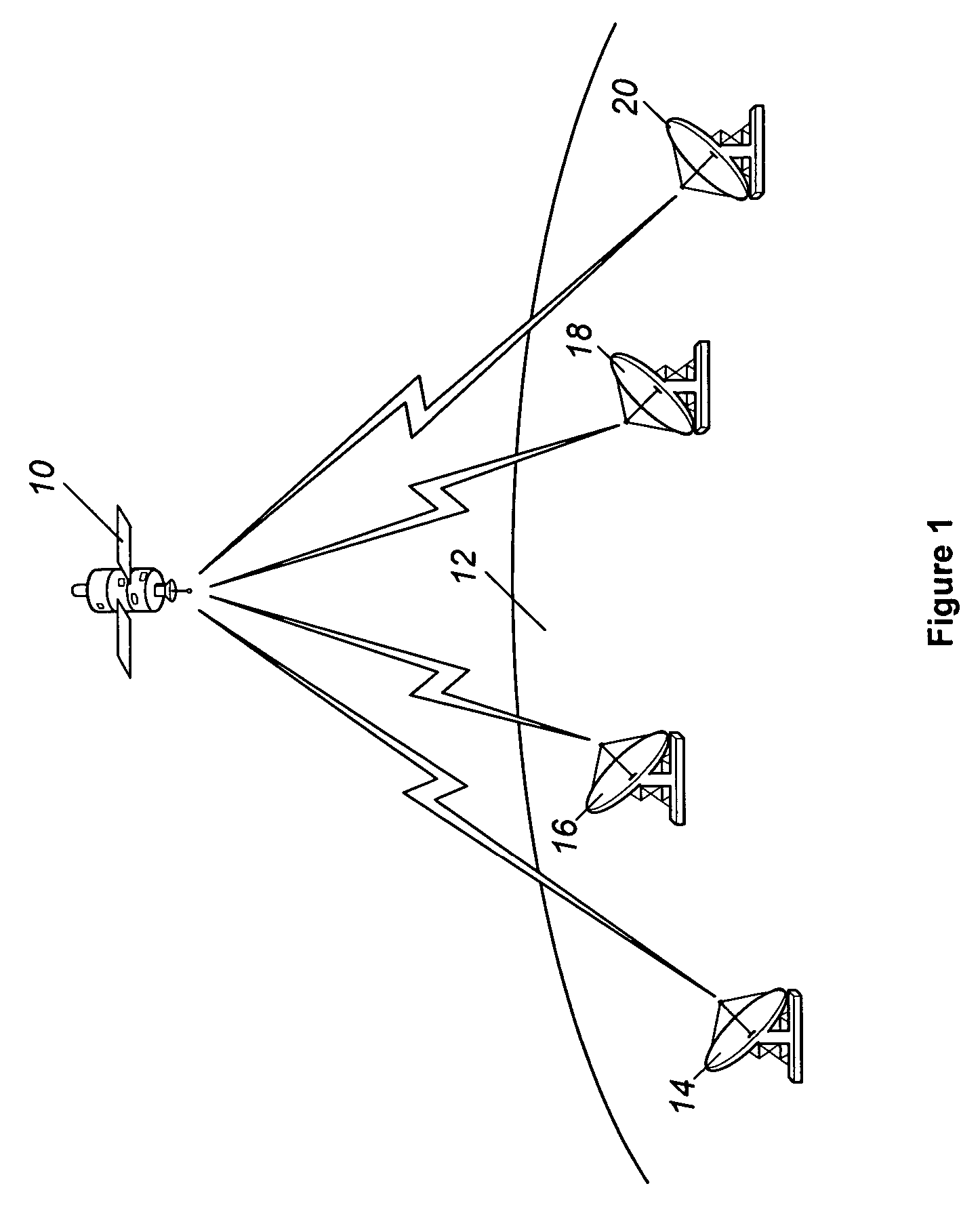
[0012]FIG. 1 is a schematic representation of a preferred embodiment of a communication system operating in accordance with the present invention. A satellite 10 is operating in an earth orbit above the surface of the earth 12. A plurality of ground stations 14, 16, 18, 20 are capable of communicating through satellite 10. Thus, for example, ground station 14 might transmit a signal including a plurality of messages to satellite 10. Satellite 10 processes these messages and relays separate messages to appropriate ones of the ground stations 16, 18 and 20, as well as to other ground stations. Likewise, ground stations 16, 18, 20 might transmit a signal to satellite 10 with messages that are relayed to other ground stations.
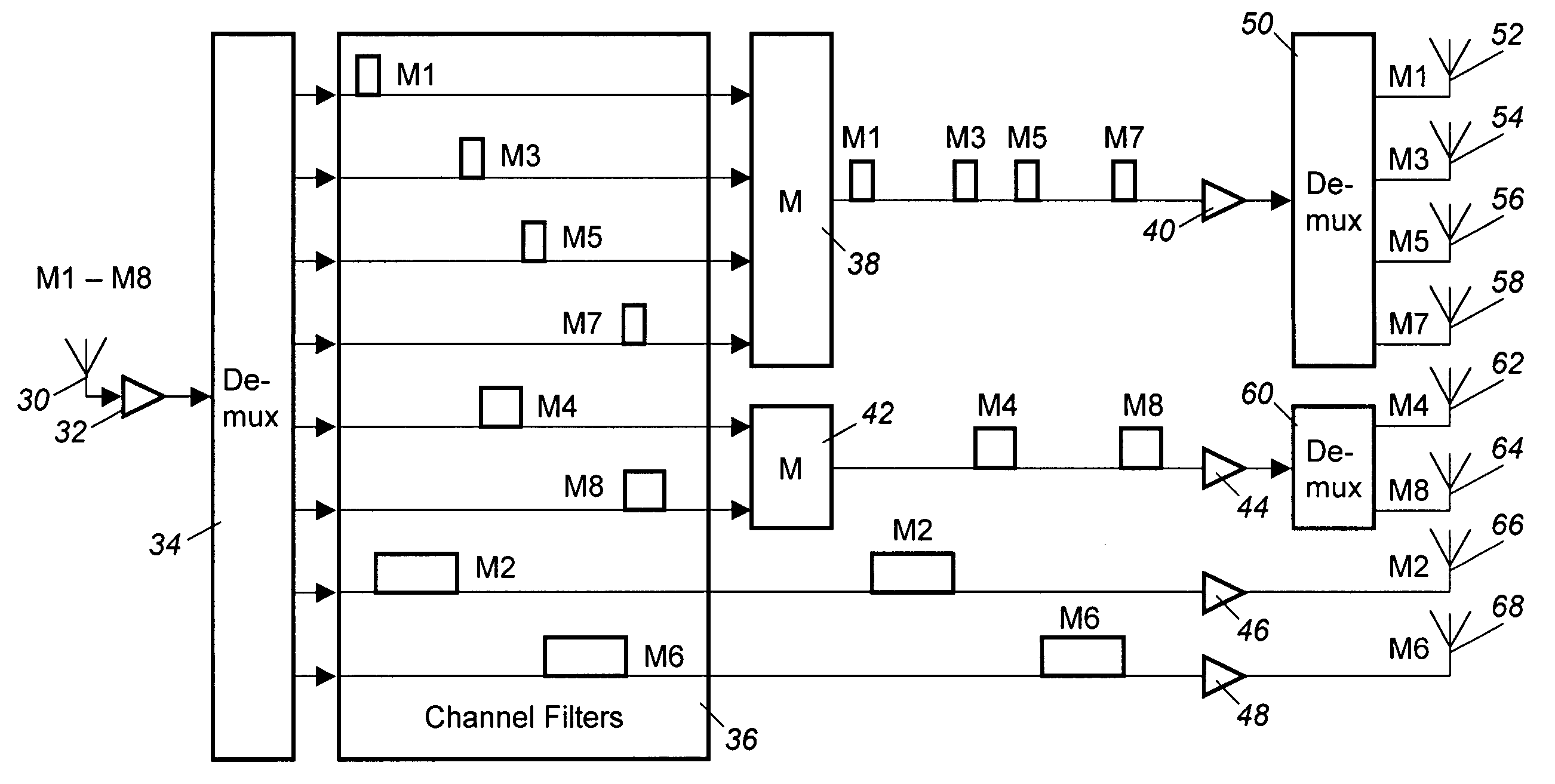
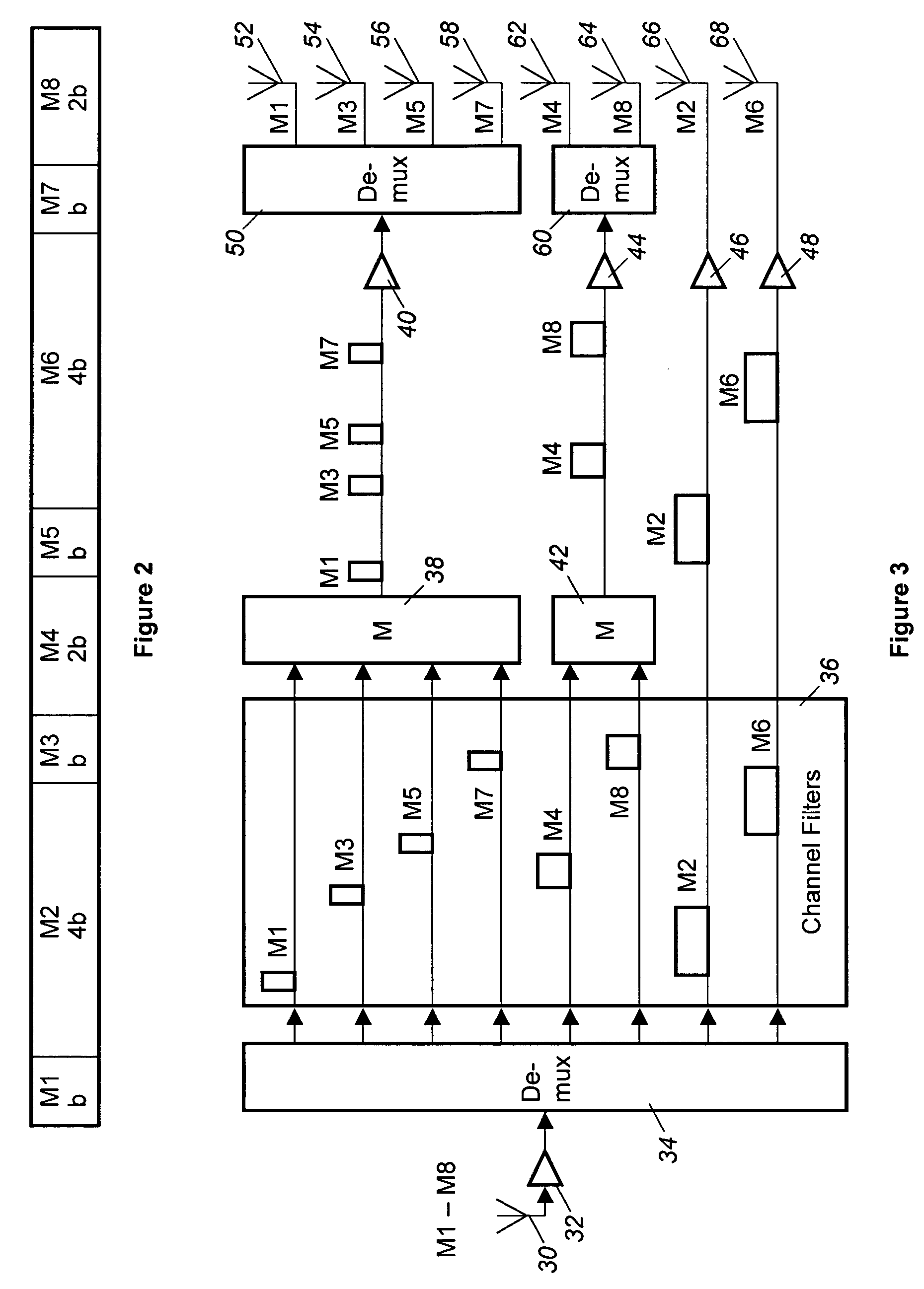
[0013]FIG. 2 illustrates a typical allocation of bandwidth to N separate messages within a signal in accordance with a preferred embodiment of the present invention. Each of the N messages has a unique frequency band with an associated bandwidth, but more than one message way have the same bandwidth. In the illustrative example of FIG. 2, the signal has a total bandwidth 16b and includes eight messages M1-M8. Message M1 is illustrated as having a bandwidth b, message M2 a bandwidth 4b, message M3 a bandwidth b, message M4 a bandwidth 2b, message M5 a bandwidth b, message M6 a bandwidth 4b, message M7 a bandwidth b, and message M8 a bandwidth 2b. FIG. 2, however, is only one illustration of bandwidth allocation. The total bandwidth B of the signal might be allocated in any manner among N messages, with the bandwidths of the messages occupying the full bandwidth B.
[0014]FIG. 3 is a block diagram of an apparatus for processing signals in a relaying station such as satellite 10 in accordance with a preferred embodiment of the present invention. The signals, illustrated in FIG. 3 as the signals M1-M8 of FIG. 2, are received by receiving antenna 30, amplified within an amplifier 32, and applied to a demultiplexor 34. Demultiplexor 34 separates the eight signals and applies them to a set of channel filters 36 which group the signals by bandwidth. Thus, signals M1, M3, M5 and M7, each of which has a bandwidth b, are applied by channel filters 36 to a combining circuit 38 which combines these signals of bandwidth b and applies the combined signals to a first traveling wave tube amplifier 40. Similarly, channel filters 36 apply signals M4 and M8, each of which has a bandwidth 2b, to a second combining circuit 42 which combines the two signals and applies the combined signals to a second traveling wave tube amplifier 44. Channel filters 36 apply the signal M2 and M6, each of which has a bandwidth 4b, directly to respective third and fourth traveling wave tube amplifiers 46 and 48. FIG. 3 illustrates the frequency separation between the signals, depicting the frequency spacing between signals M1, M3, M5 and M7 which are applied to traveling wave tube amplifier 40 and the frequency spacing between signals M4 and M8 which are applied to traveling wave tube amplifier 44. Combining circuits 38 and 42 might be multiplexors or any other suitable circuit for combining the signals applied to them.
[0015] The signals M1, M3, M5, and M7 are applied by traveling wave tube amplifier 40 to demultiplexor 50 which applies the M1 signal to a transmitting antenna 52, the M3 signal to a transmitting antenna 54, the M5 signal to a transmitting antenna 56, and the M7 signal to a transmitting antenna 58. Likewise, traveling wave tube 44 applies the M4 and M8 signals to demultiplexor 60 which applies the M4 signal to a transmitting antenna 62 and the M8 signal to a transmitting amplifier 64. Traveling wave tube 46 applies the M2 signal directly to a transmitting antenna 66, while traveling wave tube amplifier 48 applies the M6 signal directly to a transmitting antenna 68. The signals M1-M8 are thus transmitted to respective receiving stations.
[0016] Because the messages passing through any one traveling wave tube amplifier are in frequency bands separated by other frequencies, minimal channel passband gain and phase distortion is experienced. The N messages are processed by fewer traveling wave tube amplifiers, significantly reducing the number of traveling wave tube amplifiers required. Messages M2 and M6 in FIGS. 2 and 3 could be combined, amplified in a single traveling wave tube amplifier, and demultiplexed, if desired.
[0017] The bandwidth allocation need not necessarily be that depicted in FIG. 2. Other allocations could easily be accommodated, so long as no two messages having adjacent frequency bands have the same bandwidth and are applied to the same traveling wave tube amplifier. The frequency allocation must result in a frequency separation between the signals applied to any one traveling wave tube amplifier, as illustrated in FIG. 3.
[0018] Although the present invention has been described with reference to preferred embodiments, various alterations, rearrangements, and substitutions could be made, and still the result would be within the scope of the invention.

PUM

no PUM

Description & Claims & Application Information

We can also present the details of the Description, Claims and Application information to help users get a comprehensive understanding of the technical details of the patent, such as background art, summary of invention, brief description of drawings, description of embodiments, and other original content. On the other hand, users can also determine the specific scope of protection of the technology through the list of claims; as well as understand the changes in the life cycle of the technology with the presentation of the patent timeline. Login to view more.

Similar technology patents

Classification and recommendation of technical efficacy words

  • reduce number

Programming non-volatile memory

ActiveUS6888758B1short program timereduce number
Owner:SANDISK TECH LLC

Personalized display of health information

InactiveUS20050027562A1reduce number
Owner:HEALTH HERO NETWORK

Display device

Owner:SEMICON ENERGY LAB CO LTD
Why Eureka
Try Eureka