Antenna stent device for wireless, intraluminal monitoring

a technology of intraluminal monitoring and antenna, which is applied in the field of intraluminal devices, can solve the problems of not sufficiently teaching or suggesting to one of ordinary people, complex implementation and deployment of such devices, and re-closures that occur, etc., and achieve the effect of maintaining the patency of the lumen

Active Publication Date: 2005-04-14
RGT UNIV OF MICHIGAN OFFICE TECH TRANSFER
View PDF21 Cites 175 Cited by
  • Summary
  • Abstract
  • Description
  • Claims
  • Application Information

AI Technical Summary

Benefits of technology

In one embodiment, the non-helical configuration includes a planar set of involute bands. Alternatively, the non-helical configuration includes a plurality of cross bands coupled via a beam having a breakable link for disconnecting adjacent cross bands of the plurality of cross bands upon deployment to form the helical scaffolding. The stent structure may be further capable of plastic deformation to form a non-helical scaffolding structurally coupled to the helical scaffolding for maintaining the patency of the lumen. The non-helical scaffolding may include a pair of rings coupled to the helical scaffolding at respective longitudinal ends of the helical scaffolding.
In accordance with another aspect, a device for maintaining patency of a lumen while monitoring an intraluminal characteristic of the lumen includes a sensor and a scaffolding. The sensor is responsive to the intraluminal characteristic of the lumen to generate a signal indicative thereof, and the scaffolding is deployed in the lumen and has a helical portion and a non-helical portion. The helical portion includes an inductance coupled to the sensor for wireless transmission of the signal and the non-helical portion provides structural support for maintaining the patency of the lumen.

Problems solved by technology

However, re-closures often occur due to recoil of the blood vessels, further plaque deposition, or spasms.
Despite these advances in implantable devices and wireless monitoring methods, the implementation and deployment of such devices is complicated by the presence of the thin-film inductor necessary for passive telemetry.
The prior art also does not sufficiently teach or suggest to one of ordinary skill in the art how to utilize stents, of either existing or novel design, in the implementation, deployment and operation of such implantable measurement devices.
Still further, the prior art does not sufficiently teach or suggest to one of ordinary skill in the art a stent device capable of maintaining the patency of a lumen while also monitoring one or more intraluminal characteristics.

Method used


Image

  • Antenna stent device for wireless, intraluminal monitoring
  • Antenna stent device for wireless, intraluminal monitoring
  • Antenna stent device for wireless, intraluminal monitoring

Examples


example 1

As an initial matter, it should be noted that, for an effective wireless link, minimal damping is desired in the LC tank. The quality factor is expressed as: Q≈1RSTp⁢LSTCSE+CSTp

where LST is inductance of the stent device, CSE is capacitance of the sensor, CSTp is parasitic capacitance, and RSTp is parasitic resistance. The impact of the RSTp is greater than that of CSTp. The parasitic resistance contributed by the stent inductance is inversely related to the beam cross-section, whereas the parasitic capacitance that it contributes is proportional to the beam surface area. Therefore, RSTp depends on the square of the beam diameter whereas CSTp is simply proportional to it. Thus, it is electrically favorable to increase the thickness of the beams. In fact, this is favorable mechanically as well, because it would increase the radial stiffness of the stent. However, from the biological viewpoint, increasing the volume of the structural elements can be undesirable, which may warrant a...

example 2

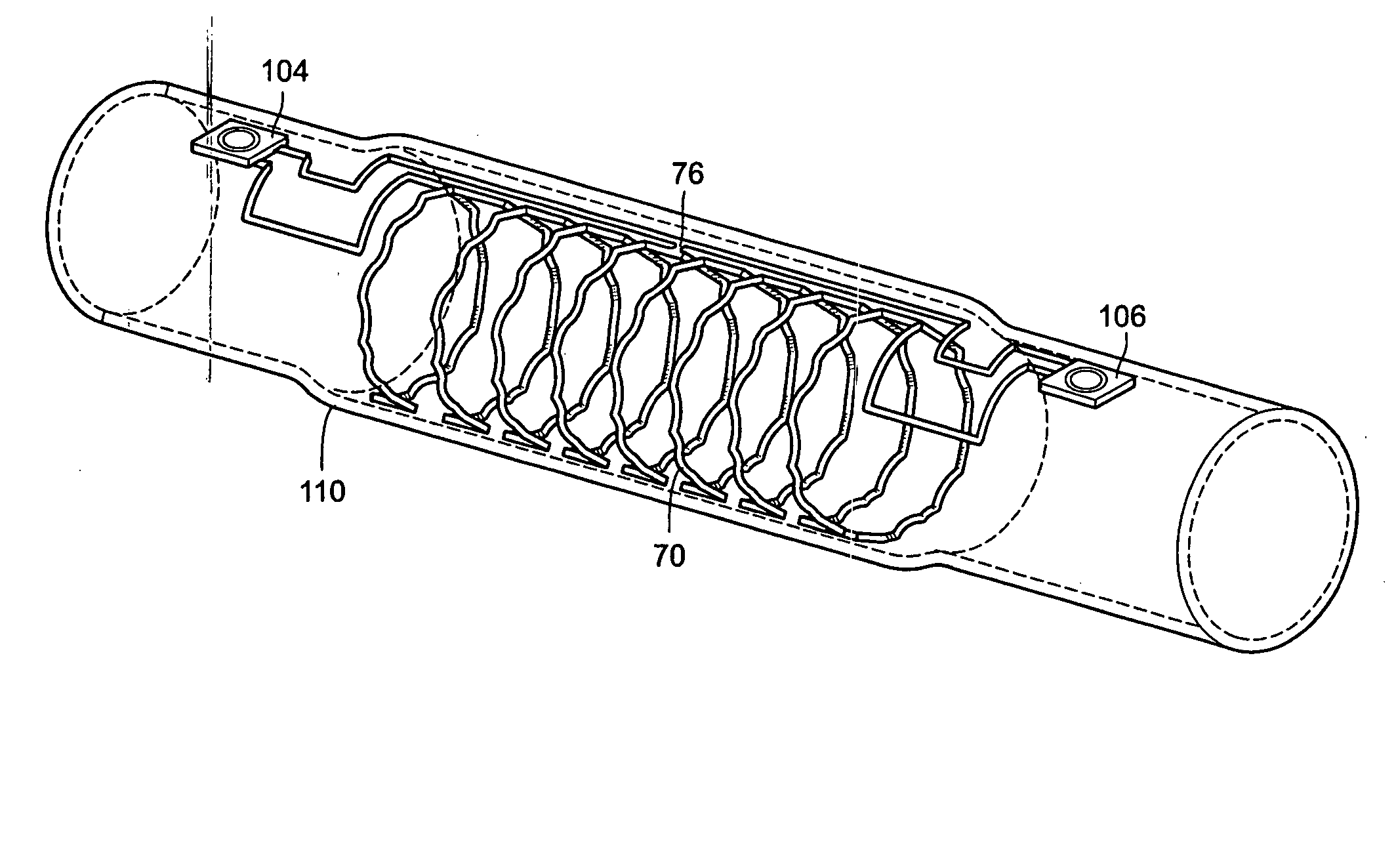
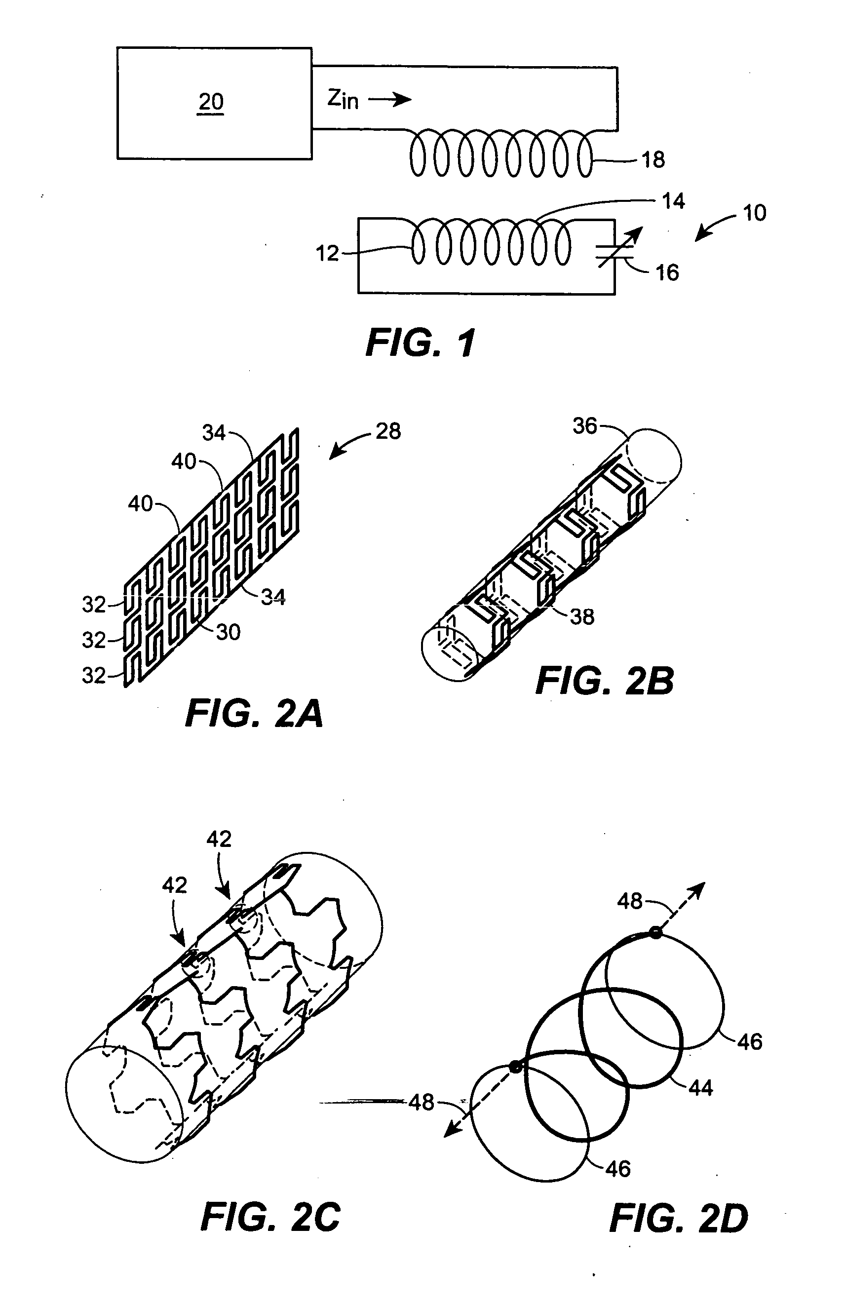
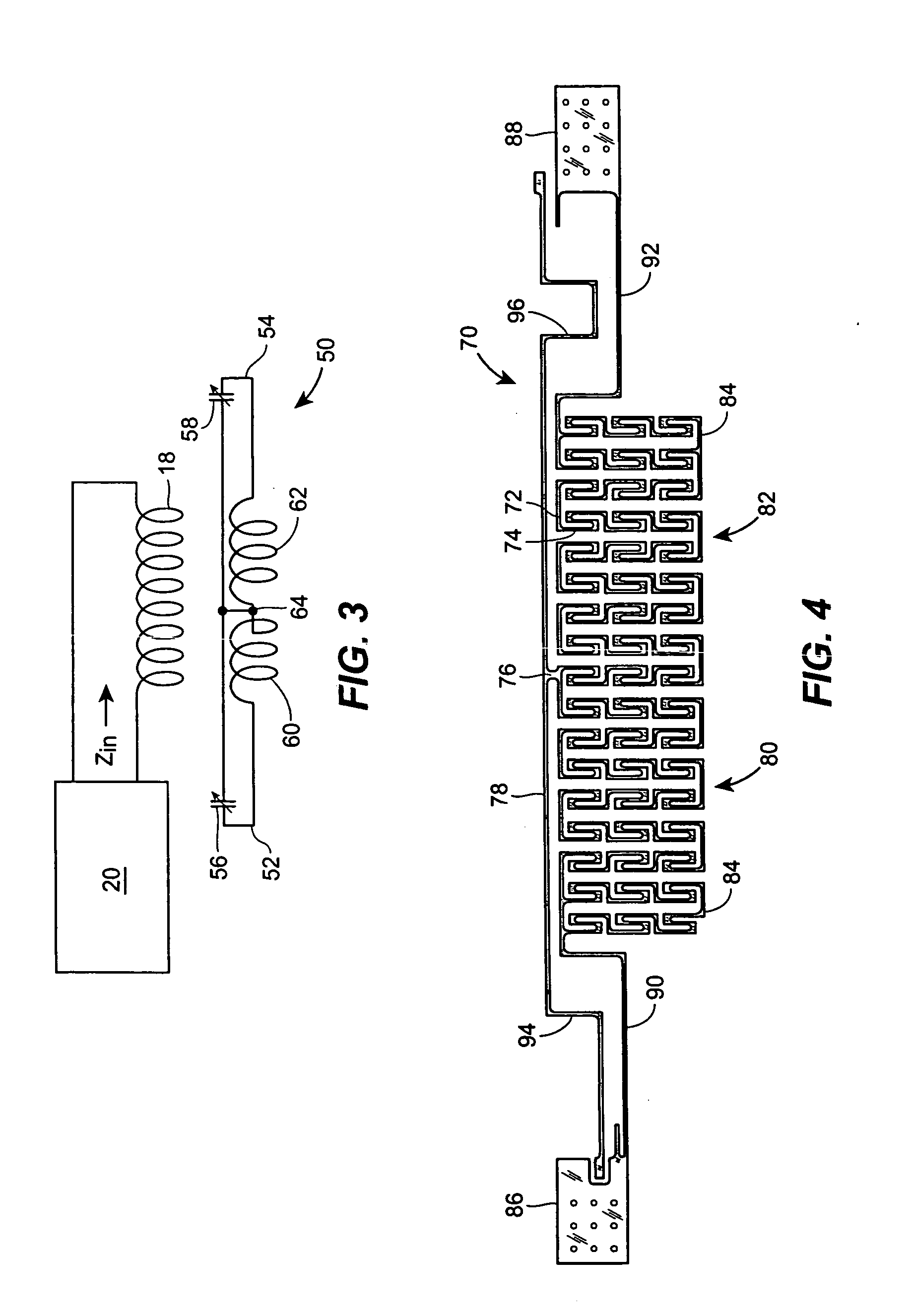
This example presents a micromachined antenna stent device that is integrated with two implantable microsensors for wireless sensing of blood flow and pressure with no battery. A device that has 20-mm length and 3.5-mm diameter (after expansion) is fabricated from 50 μm thick stainless steel foil by using batch-compatible micro-electro-discharge machining. This is coupled to two micromachined capacitive pressure sensors of approximately 1.4×1.8×0.5 mm3 dimensions. A 0.5-μm thick parylene layer provides electrical insulation. The integrated device is deployed inside a silicone mock artery with a standard angioplasty balloon. The planar structure is plastically deformed to a tubular shape, resulting in dual helical coils with 50-60 nH each. These L-C tanks are used to wirelessly probe pressures at two points along a channel for flow-rate detection. Fluidic experiments that emulate a blockage in the mock artery demonstrate that the resonant impedance and phase provided by the LC-tanks...


PUM

PropertyMeasurementUnit
diameteraaaaaaaaaa
diameteraaaaaaaaaa
inductanceaaaaaaaaaa

Abstract

Disclosed herein is a stent device useful for maintaining the patency of a lumen while monitoring an intraluminal characteristic. The device includes a structure having a set of extendible bands that are capable of plastic deformation to form a scaffolding having an inductance, and further includes a capacitance coupled to the set of extendible bands and responsive to the intraluminal characteristic. The capacitance and the inductance form a tank circuit after the plastic deformation of the set of extendible bands to enable wireless transmission of an indication of the intraluminal characteristic.

Description

BACKGROUND OF THE INVENTION 1. Field of the Invention The invention generally relates to intraluminal devices and, more particularly, devices used to monitor intraluminal characteristics. 2. Brief Description of Related Technology In recent years, stents have come to play an essential role in the treatment of cardiovascular diseases. A stent typically has mesh-like walls in a tubular shape, and once positioned by a catheter, is expanded radially by the inflation of an angioplasty balloon. Stents are implanted by such procedures to physically expand and scaffold coronary and other arteries that have been narrowed by plaque. However, re-closures often occur due to recoil of the blood vessels, further plaque deposition, or spasms. Monitoring of blood flow can provide advance notice of such failures and, thus, continuing measurement of blood flow is therefore important for long-term monitoring of vascular diseases. Implantable pressure sensors are promising devices for continuous m...

Claims


Application Information

Patent Timeline
Patent Type & Authority Applications(United States)
IPC IPC(8): A61F2/06A61F2/90B23H9/00
CPCB23H9/00A61F2/91
Inventor GIANCHANDANI, YOGESH B.TAKAHATA, KENICHIWISE, KENSALL D.DEHENNIS, ANDREW D.
Owner RGT UNIV OF MICHIGAN OFFICE TECH TRANSFER
Why Eureka
Try Eureka