Ultrasonic slitter

a technology of ultrasonic slitter and slitter blade, which is applied in the direction of metal working apparatus, meat shaping/cutting, manufacturing tools, etc., can solve the problems of excessive mechanical vibration, poor cutting, and limited cutting speed of guillotine blades, so as to increase the engagement of food products

Inactive Publication Date: 2005-04-21
KRAFT FOODS INC
View PDF22 Cites 28 Cited by
  • Summary
  • Abstract
  • Description
  • Claims
  • Application Information

AI Technical Summary

Benefits of technology

[0007] The first and second cutting edges are preferably downwardly convergent, defining an included angle greater than 60 degrees and less than 90 degrees. In one particular embodiment, the internal angle is 70 degrees. In another embodiment, the angle is about 60 degrees.
[0008] The cutting edges preferably are inclined at identical angles, and preferably intersect a horizontal bottom edge of the blade at identical obtuse angles. The food product preferably has generally vertical sides so that the transverse engagement of the food product by the blade results in initial engagement of an upper corner portion of the food product by the blade, followed by continuously increasing engagement of the food product by the blade as the depth of penetration increases, with the blade moving horizontally and the resultant force on the food product being a vector having a downward component as well as a transverse horizontal component. The blade may have a linear translating velocity of 25 to 35 inches per second, and more specifically may have a transverse velocity of approximately thirty inches per second.
[0009] The apparatus may further include a stationary frame and a carriage translatably secured to the frame so as to be movable transversely relative to the direction of movement of the food product, where the carriage includes the blade and a head supporting the blade and providing ultrasonic mechanical vibration to the blade.
[0010] In one form, the conveyor may include conveyor sections separated by a gap, and an anvil positioned between the conveyor sections. The food product may pass over a bottom portion of the anvil and between side portions of the anvil as the food product is advanced by the conveyor, and the anvil preferably is capable of supporting and constraining the food product against downward displacement and against transverse displacement in either horizontal transverse direction. The anvil may include various elements for engaging the food product such as rotating elements, moving belts or O-rings, or stationary elements. The anvil preferably has a groove or channel in its lower portion having a width slightly greater than that of the blade to permit a lower portion of the blade to pass below a bottom surface of the food product as the food product is being cut. The anvil also preferably has side gaps which have a width greater than the thickness of the blade to permit the blade or portions thereof to pass through laterally beyond the sides of the anvil.
[0011] The frame may be secured to a base, and may include one or more rails for guiding lateral translation of the carriage. The carriage may include a slide translatably secured on each rail. The device may include a drive slide to which translating force is provided, and a drive rail to which the drive slide is translatably secured. The head may include a signal generator and an amplifier to provide mechanical oscillation to the blade.
[0012] The invention may be used in high-speed, high-volume commercial food production operations for automated cutting of cheese products and other food products from large chunks, slabs and the like into smaller portions, and may also be used in other applications.

Problems solved by technology

The weight of the guillotine and associated transducer and amplifier results in practical limitations on the length of the guillotine blade and the speed at which the blade can be reciprocated.
Increasing the linear velocity beyond 18 in. per second results in excessive mechanical vibration.
This produces poor cutting results, and creates stress which may damage system components.

Method used


Image

  • Ultrasonic slitter
  • Ultrasonic slitter
  • Ultrasonic slitter

Examples


Embodiment Construction

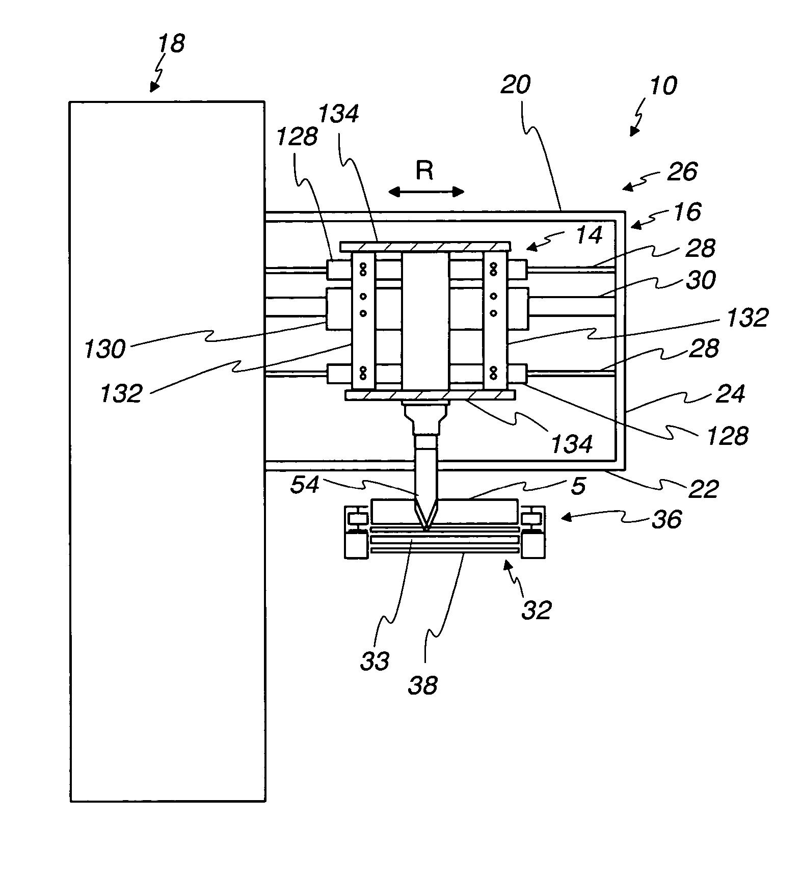
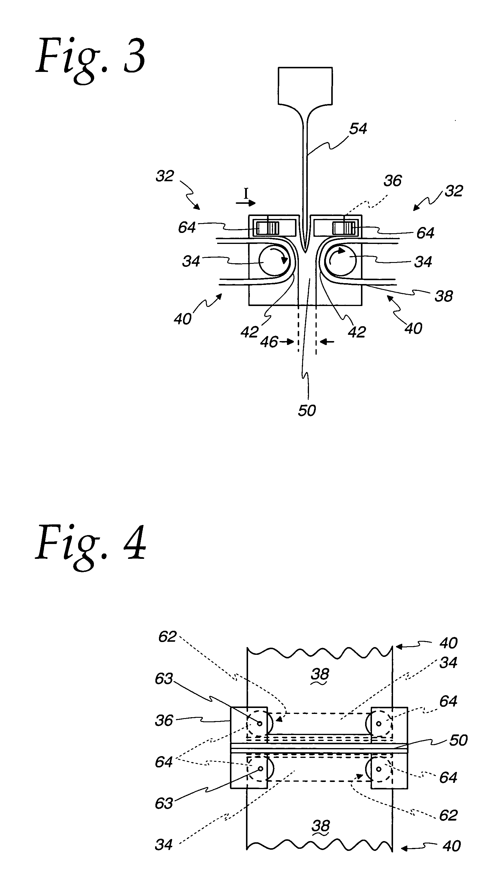
[0019] Referring initially to FIG. 1, the invention is preferably embodied in a bidirectional ultrasonic slitter 10 including a translatable carriage 14 supported on a frame 16 on a base 18. As described below, the slitter 10 forms transverse cuts in a food product slab 5 supported on a conveyor assembly 32 that includes an anvil 36 disposed between a pair of conveyors.

[0020] The structure of the apparatus may take various different forms. One particular structure is described below and shown in the drawings for purposes of example.

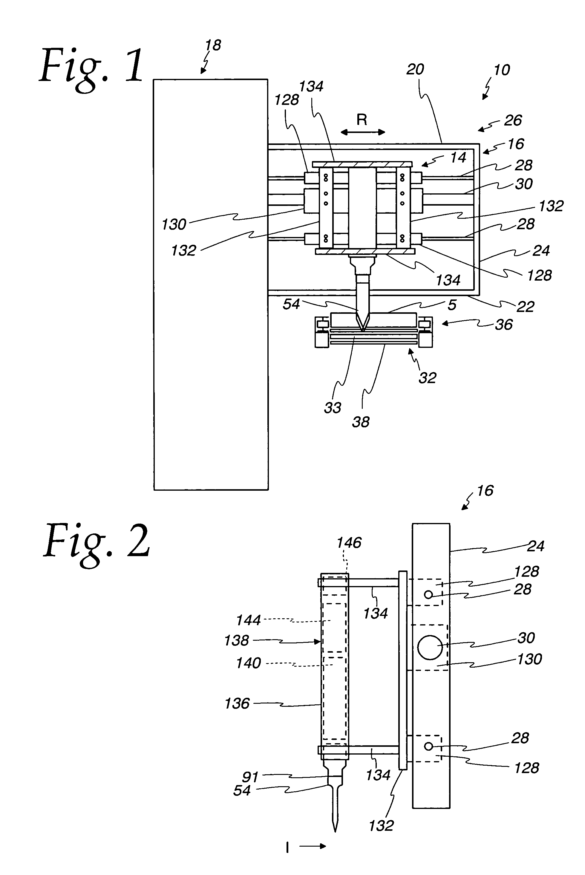
[0021] The illustrated base 18 includes operator controls and provides power for translation to the carriage 14. The illustrated frame 16 includes horizontal transverse top and bottom members 20 and 22 supporting a vertical side member 24. Guide rails 28 and drive rail 30 extend horizontally and parallel to one another transversely over the conveyor, supported at opposite ends by the base 18 and side member 24 respectively. The carriage 14 is slidably s...


PUM

PropertyMeasurementUnit
frequencyaaaaaaaaaa
included angleaaaaaaaaaa

Abstract

Apparatus for high-volume, high speed ultrasonic cutting or slitting comprising a blade having first and second cutting edges suspended from a reciprocating head, cantilevered over a conveyor supporting and advancing the food product, with the blade including first and second cutting edges on respective opposite sides thereof to cut the food product transversely. The head is preferably controlled for automated operation by an electronic controller to reciprocate transversely at a selected speed and a selected frequency within predetermined ranges over food product advancing on the conveyor. The blade preferably oscillates ultrasonically, and preferably at a frequency of approximately 20,000 Hz. The first and second cutting edges are preferably downwardly convergent, defining an included angle greater than 60 degrees and less than 90 degrees. In one particular embodiment, the internal angle is 70 degrees. In another embodiment, the angle is about 60 degrees. The blade may have a linear translating velocity of 25 to 35 inches per second, and more specifically may have a transverse velocity of approximately thirty inches per second. The apparatus may be used in high-speed, high-volume commercial food production operations for automated cutting of cheese products and other food products from large chunks, slabs and the like into smaller portions, and may also be used in other applications.

Description

FIELD OF THE INVENTION [0001] The invention relates to apparatus for cutting food products such as cheese products, and specifically to an ultrasonic slitter. BACKGROUND OF THE INVENTION [0002] U.S. Pat. No. 6,403,138, incorporated by reference herein, describes use of a particular type of ultrasonic cutting apparatus in connection with making retail-sized cheese chunks in a continuous process. Various other types of cutting apparatus are used in other high-speed, high-volume commercial food production operations for automated cutting of cheese products and other food products from large chunks, slabs and the like into smaller portions. [0003] In certain high speed commercial operations for manufacturing, packaging, and otherwise processing food products, ultrasonic cutting apparatus may be preferable to conventional blades for a number of reasons. Ultrasonic blades may provide a superior quality of cut by avoiding adherence of food products such as nougat or icing, and may also be ...

Claims


Application Information

Patent Timeline
Patent Type & Authority Applications(United States)
IPC IPC(8): B26D3/00A01J25/12A22B5/00A22C17/00A22C25/18A23C19/00B26D1/00B26D3/08B26D3/24B26D5/08B26D7/00B26D7/08
CPCA01J25/12A22B5/0029A22C17/0006B26D7/086B26D1/18B26D3/24A22C25/18Y10T83/7876Y10T83/8822Y10T83/97A23C19/00B26D1/00B26D5/08B26D7/00
Inventor MOSIEWICZ, KRZYSZTOFARORA, VIJAY K.
Owner KRAFT FOODS INC
Why Eureka
Try Eureka