Gripper assembly for downhole tools

a technology for tools and grippers, which is applied in the direction of drilling rods, drilling pipes, borehole/well accessories, etc., can solve the problems of large pressure drop in flow-by fluid, too large gripper designs to fit within the small dimensions of boreholes, and limited radial expansion capabilities, so as to achieve less effective and limited radial expansion loads

Inactive Publication Date: 2005-04-21
WWT NORTH AMERICA HLDG
View PDF56 Cites 36 Cited by
  • Summary
  • Abstract
  • Description
  • Claims
  • Application Information

AI Technical Summary

Benefits of technology

[0011] Yet another type of gripper comprises a combination of bladders and flexible beams oriented generally parallel to the tractor body on the radial exterior of the bladders. The ends of the beams are maintained at a constant radial position near the surface of the tractor body, and may be permitted to slide longitudinally. Inflation of the bladders causes the beams to flex outwardly and contact the borehole wall. This design effectively separates the loads associated with r

Problems solved by technology

Tractors for moving within downhole passages are often required to operate in harsh environments and limited space.
As a result of the harsh working environment, space constraints, and desired force generation requirements, downhole tractors are used only in very limited situations, such as within existing well bore casing.
However, these gripper designs are either too large to fit within the small dimensions of a borehole or have limited radial expansion capabilities.
Also, the size of these grippers often cause a large pressure drop in the flow-by fluid, i.e., the fluid returning from the drill bit up through the annulus between the tractor and the borehole.
The pressure drop makes it harder to force the returning fluid up to the surface.
Also, the pressure drop may cause drill cuttings to drop out of the main fluid path and clog up the annulus.
While inflatable bladders provide good conformance to the possibly irregular dimensions of a borehole, they do not provide very good torsional resistance.
In other words, bladders tend to permit a certain degree of undesirable twisting or rotation of the tractor body, which may confuse the tractor's position sensors.
Also, some bladder configurations may substantially impede the flow-by of fluid and drill cuttings returning up through the annulus to the surface.
As a result, the design is less effective in certain environments.
Also, this design impedes to some extent the flow of fluid and drill cuttings upward through the annulus.
One major disadvantage of the three-bar linkage gripper design is that it is difficult to generate significant radial expansion loads against the inner surface of the borehole until the second link 204 has been radially displaced a substantial degree.
Thus, when the gripper is in or is near the retracted position, the gripper is incapable of transmitting any significant

Method used


Image

  • Gripper assembly for downhole tools
  • Gripper assembly for downhole tools
  • Gripper assembly for downhole tools

Examples


Embodiment Construction

Coiled Tubing Tractor Systems

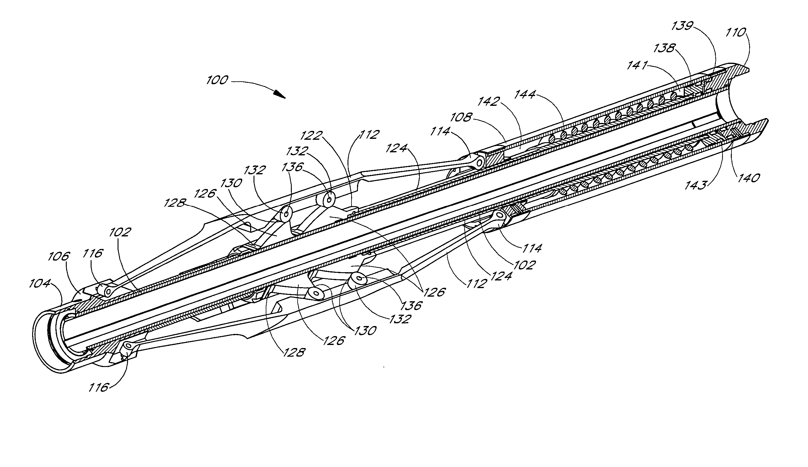
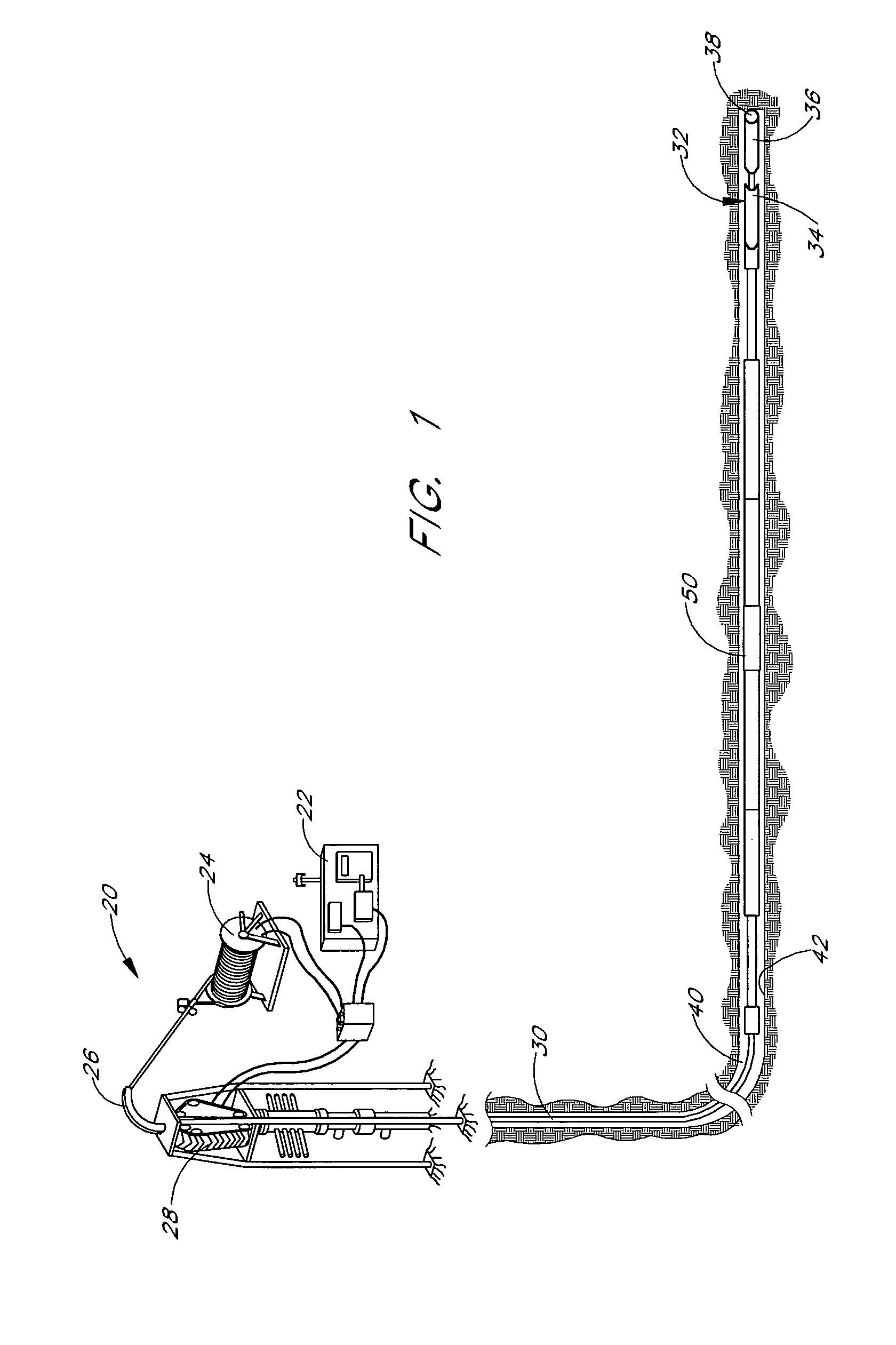
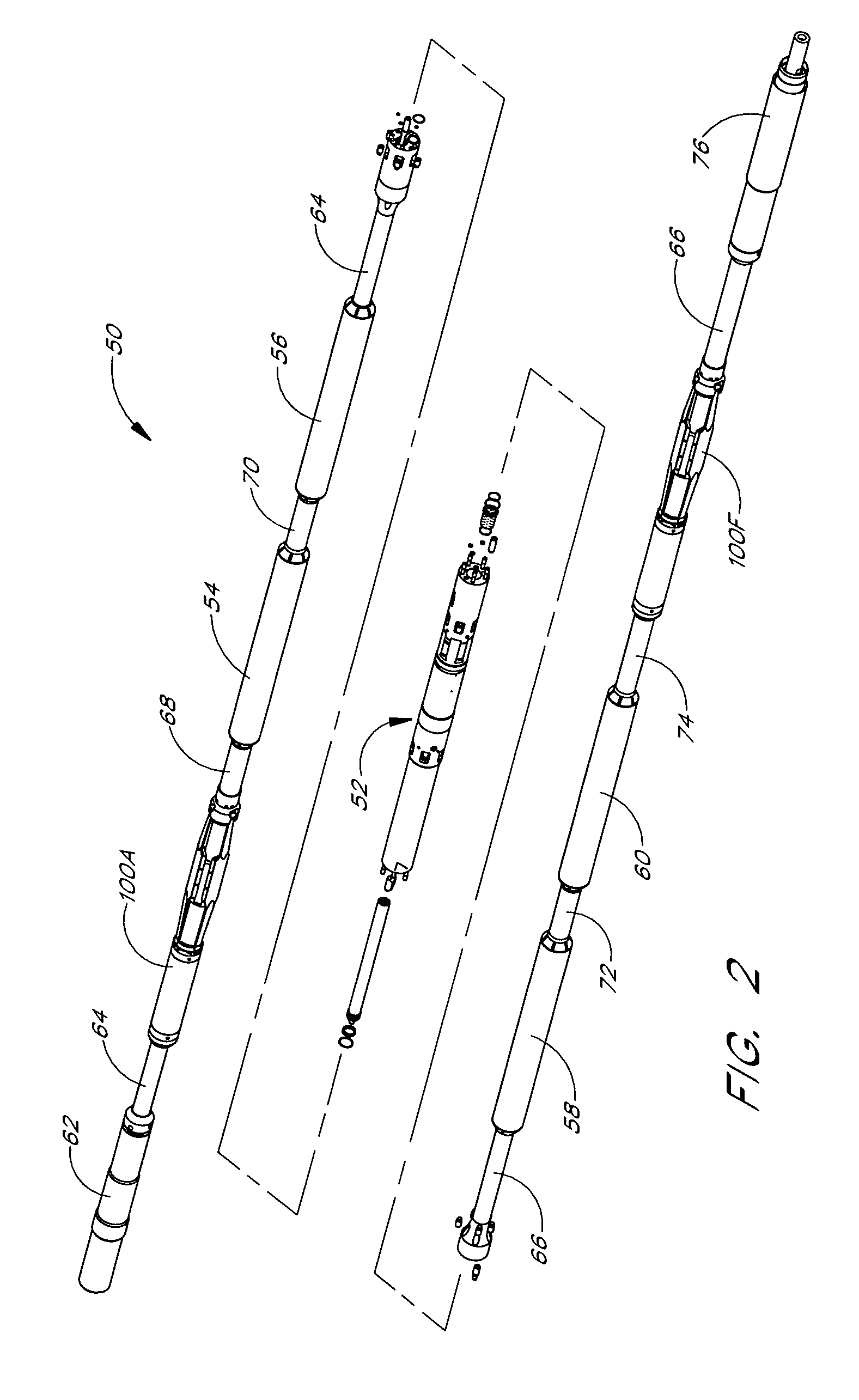
[0048]FIG. 1 shows a coiled tubing system 20 for use with a downhole tractor 50 for moving within a passage. The tractor 50 has two gripper assemblies 100 (FIG. 2) according to the present invention. Those of skill in the art will understand that any number of gripper assemblies 100 may be used. The coiled tubing drilling system 20 may include a power supply 22, tubing reel 24, tubing guide 26, tubing injector 28, and coiled tubing 30, all of which are well known in the art. A bottom hole assembly 32 may be assembled with the tractor 50. The bottom hole assembly may include a measurement while drilling (MWD) system 34, downhole motor 36, drill bit 38, and various sensors, all of which are also known in the art. The tractor 50 is configured to move within a borehole having an inner surface 42. An annulus 40 is defined by the space between the tractor 50 and the inner surface 42.

[0049] Various embodiments of the gripper assemblies 100 are described here...


PUM


Abstract

A gripper assembly for anchoring a tractor within a downhole passage and for assisting movement of the tractor within the passage. The gripper assembly includes an elongated mandrel and flexible toes that can be radially displaced to grip onto the surface of the passage. The toes are displaced by the interaction of a driver slidable on the mandrel and a driver interaction element on the toes. In one embodiment, the toes are displaced by the interaction of rollers and ramps that are longitudinally movable with respect to one another. In another embodiment, the toes are displaced by the interaction of toggles that rotate with respect to the toes.

Description

RELATED APPLICATIONS [0001] This application claims the benefit under 35 U.S.C. § 120 of U.S. patent application Ser. No. 10 / 268,604, filed Oct. 9, 2002, which claims the benefit under 35 U.S.C. § 120 of U.S. patent application Ser. No. 09 / 777,421, filed Feb. 6, 2001, now U.S. Pat. No. 6,464,003, which claims the benefit under 35 U.S.C. § 119 of U.S. Provisional Patent Application Ser. No. 60 / 182,995, entitled “FLUID POWERED FLEXTOE PACKERFOOT,” filed on Feb. 16, 2000; U.S. Provisional Patent Application Ser. No. 60 / 205,937, entitled “PACKERFOOT IMPROVEMENTS,” filed on May 18, 2000; and U.S. Provisional Patent Application Ser. No. 60 / 228,918, entitled “ROLLER TOE GRIPPER,” filed on Aug. 29, 2000. Each of the above-identified applications is hereby incorporated by reference in its entirety.FIELD OF THE INVENTION [0002] The present invention relates generally to grippers for downhole tractors and, specifically, to improved gripper assemblies. DESCRIPTION OF THE RELATED ART AND SUMMARY...

Claims


Application Information

Patent Timeline
IPC IPC(8): E21B4/18E21B23/00E21B23/01E21B23/04
CPCE21B4/18E21B19/22E21B2023/008E21B23/01E21B23/04E21B23/00E21B23/001E21B23/04115E21B17/1021E21B31/20E21B17/20E21B23/10
Inventor BLOOM, DUANEMOORE, NORMAN BRUCEKRUEGER, RUDOLPH ERNST V
Owner WWT NORTH AMERICA HLDG
Why Eureka
Try Eureka