Starter for cranking internal combustion engine

a technology for starting engines and internal combustion engines, which is applied in the direction of engine starting, machine/engines, electric generator control, etc., can solve the problems of affecting the operation of the starter, the wire connecting the magnetic switch to the electric motor may be disconnected or cut,

Active Publication Date: 2005-04-21
DENSO CORP
View PDF4 Cites 20 Cited by
  • Summary
  • Abstract
  • Description
  • Claims
  • Application Information

AI Technical Summary

Benefits of technology

[0007] The present invention has been made in view of the above-mentioned problems, and an object of the present invention is to provide an improved starter, in which water penetration into an electric motor is prevented and a member connecting a magnetic switch to the electric motor is made resistive to vibration between.

Problems solved by technology

Therefore, there is a possibility that water splashed on the starter enters into the electric motor along the lead wire by a capillary action.
Therefore, there is a possibility that the lead wire connecting the magnetic switch to the electric motor may be disconnected or cut due to vibration transmitted from the engine.

Method used


Image

  • Starter for cranking internal combustion engine
  • Starter for cranking internal combustion engine
  • Starter for cranking internal combustion engine

Examples


first embodiment

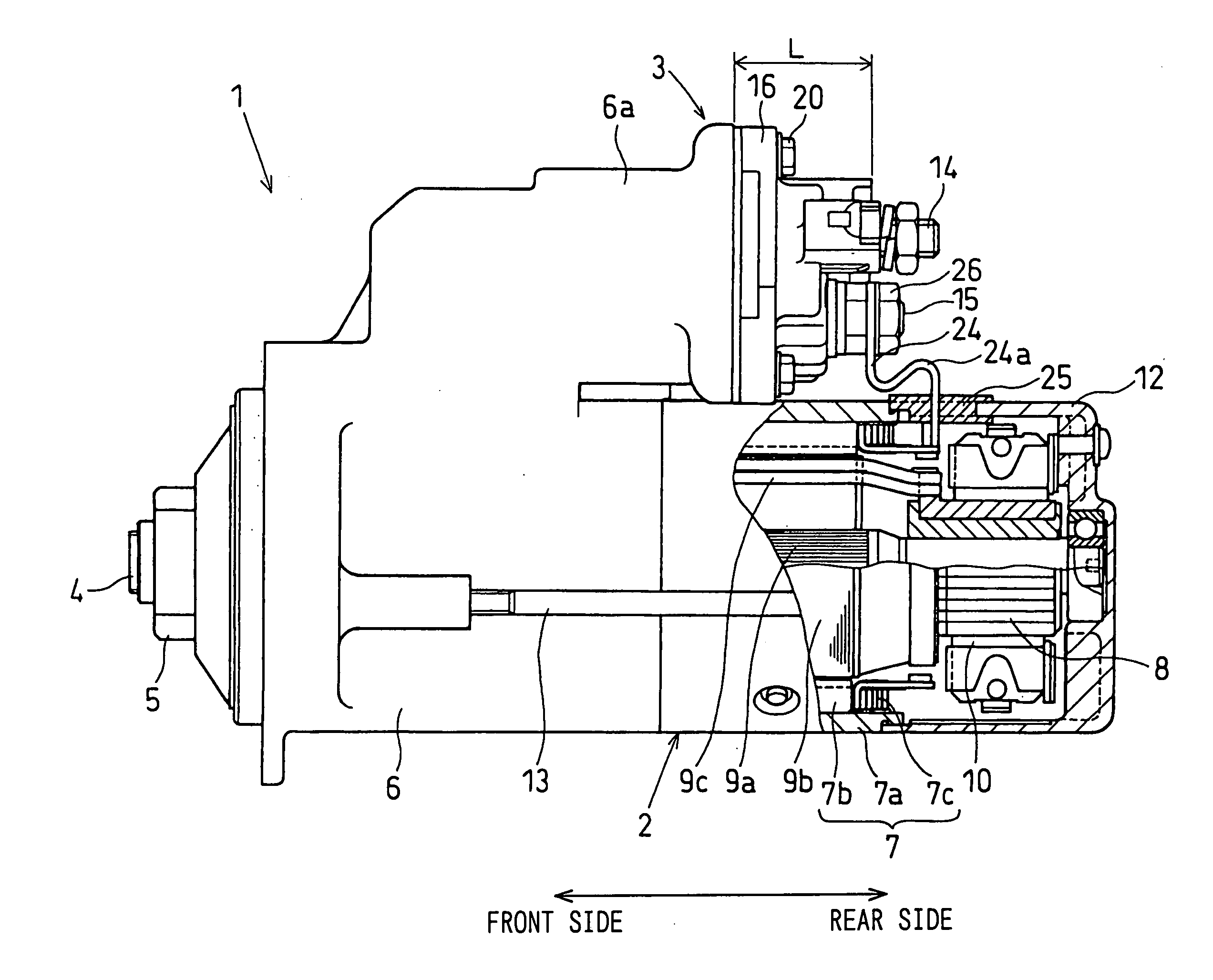
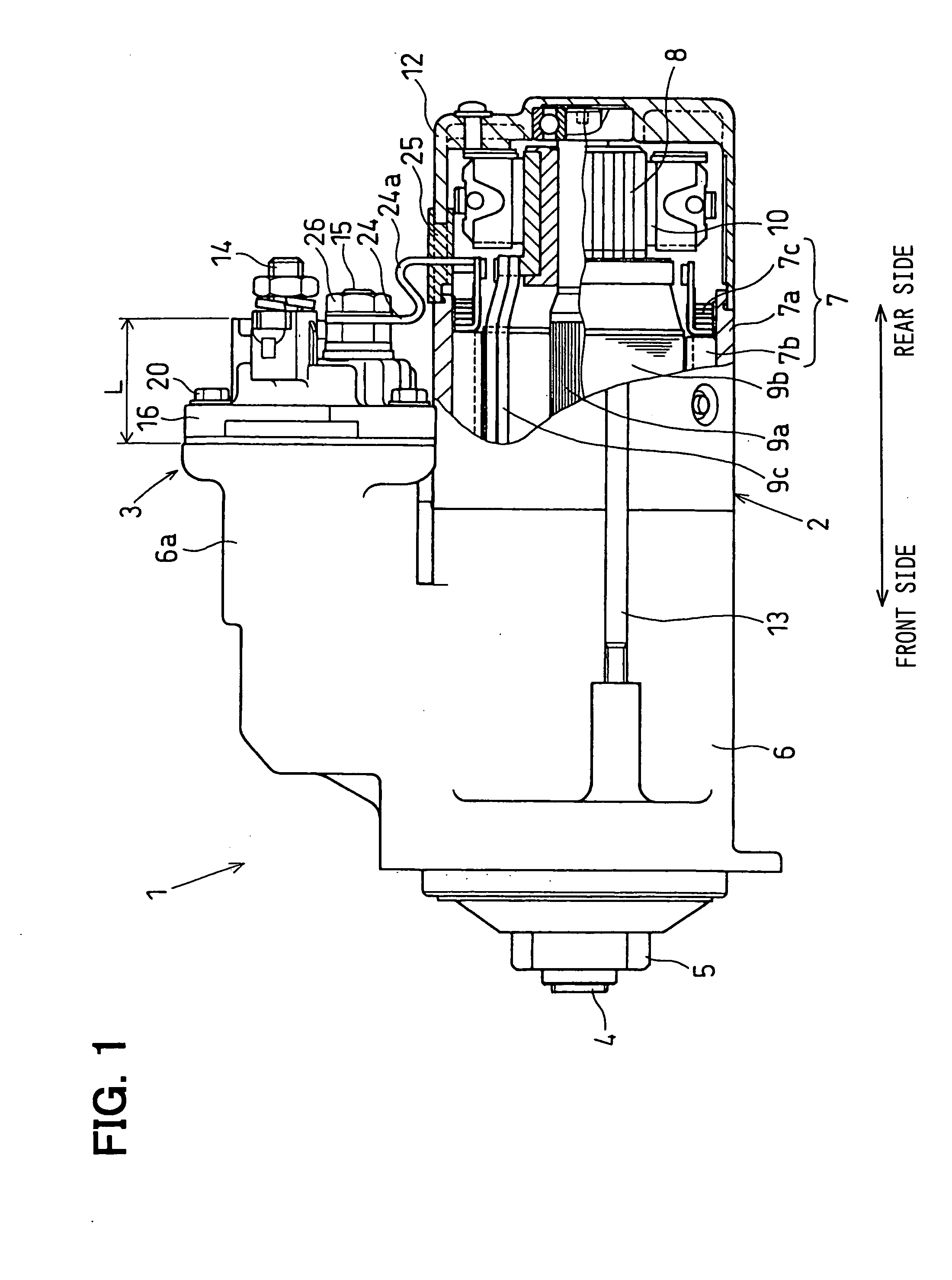
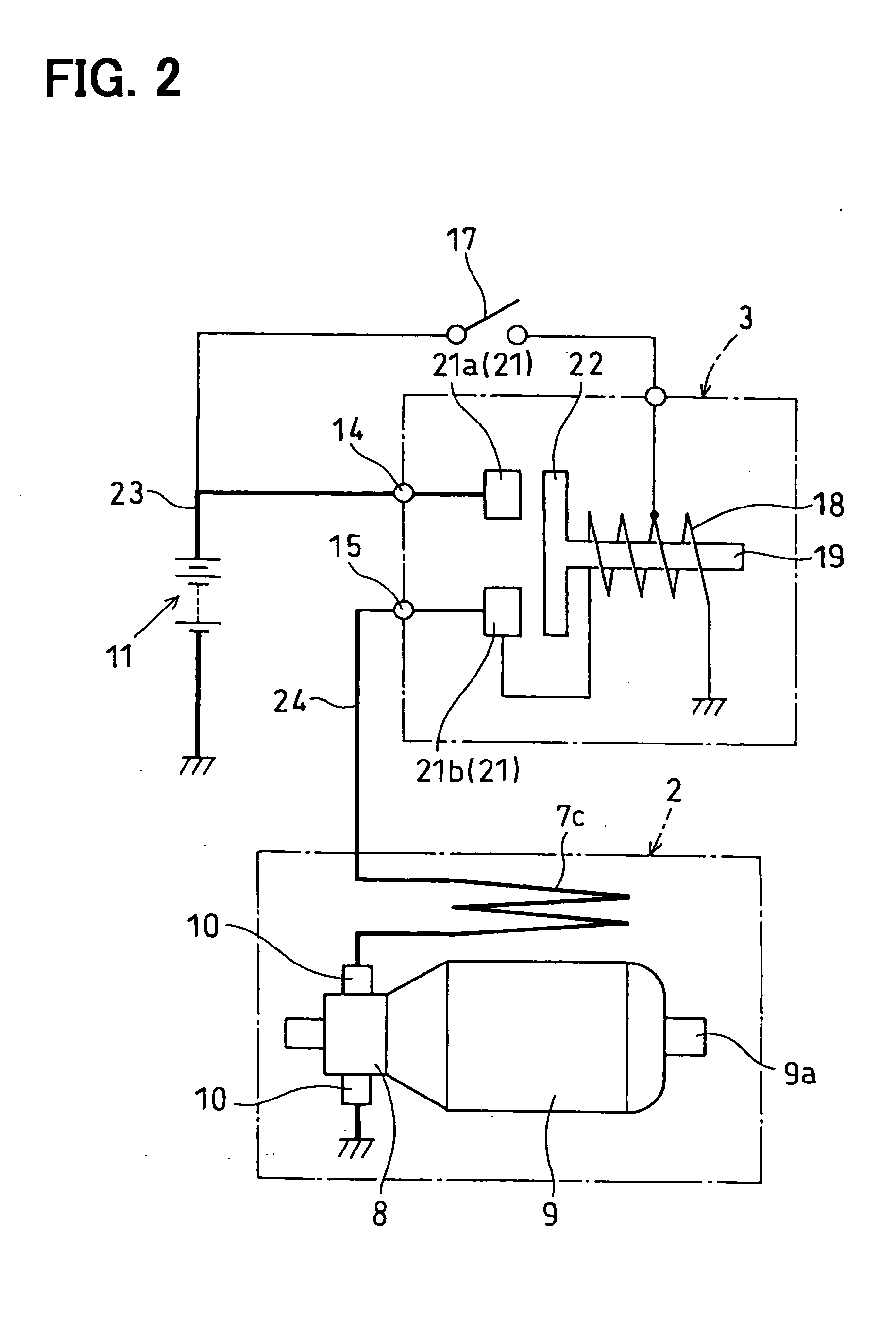
[0023] the present invention will be described with reference to FIGS. 1-3. As shown in FIG. 1, a starter 1 for cranking an internal combustion engine includes an electric motor 2, a magnetic switch 3 having a power supply circuit for supplying electric power to the electric motor, an output shaft 4 driven by the electric motor, and a pinion 5 disposed on the output shaft. The electric motor 2 and the magnetic switch 3 are connected to a common housing 6. In the housing 6, a planetary gear speed-reduction device (not shown) for reducing a rotational speed of the electric motor 2, a one-way clutch (not shown) for transmitting rotational torque of the planetary gear speed-reduction device to the output shaft 4, and a link mechanism for shifting the output shaft 4 forward together with the pinion 5 are also disposed. The link mechanism is driven by a plunger 19 (refer to FIG. 2) contained in the magnetic switch 3.

[0024] The electric motor 2 is a known type of a direct current motor, wh...

second embodiment

[0033] A motor terminal 24 as the present invention is shown in FIG. 4. In this embodiment, the motor terminal 24 is molded integrally with a rubber grommet 25 having an extended portion 25a. The extended portion 25a covers the outside surface of the motor terminal 24 to thereby improve insulation. In this embodiment, it is not necessary to forcibly insert the motor terminal 24 into the hole of the rubber grommet 25. Accordingly, possible damages to the grommet 25 to be caused in the inserting process can be avoided. Since the rubber of the grommet 25 tightly adheres to the motor terminal 24, water-tightness therebetween is further improved.

third embodiment

[0034] A motor terminal 24 as the present invention is shown in FIG. 5. In this embodiment, a connecting portion 27 connecting the second end of the motor terminal 24 to the end of the field coil 7c is covered with the rubber grommet 25. In this manner, the connecting portion 27 which is not strong against vibration is resiliently held by the grommet 25 to improve vibration-resistance.


PUM


Abstract

A starter for cranking an internal combustion engine is mainly composed of an electric motor and a magnetic switch having a battery bolt connected to an on-board battery and a motor bolt connected to the electric motor. When the magnetic switch is closed, electric power is supplied to the electric motor to thereby generate a rotational torque for cranking the engine. One end of a motor terminal is electrically connected to the motor bolt, and the other end is led into a motor casing through a rubber insulator supported on the motor casing. The motor terminal includes one or more curved portions having resiliency, and they are positioned between the rubber insulator and the motor bolt. Water penetration into the motor casing is prevented by the rubber insulator, and the vibration of the motor terminal is alleviated by resiliency of the curved portions.

Description

CROSS-REFERENCE TO RELATED APPLICATION [0001] This application is based upon and claims benefit of priority of Japanese Patent Application No. 2003-355170 filed on Oct. 15, 2003, the content of which is incorporated herein by reference. BACKGROUND OF THE INVENTION [0002] 1. Field of the Invention [0003] The present invention relates to a starter for cranking an internal combustion engine, the starter having an electric motor and a magnetic switch fixed to a common housing so that a rotating axis of the electric motor and an operating axis of the magnetic switch are positioned in parallel to each other. [0004] 2. Description of Related Art [0005] An example of this type of starter is disclosed in JP-U-61-35556. The starter disclosed therein has an electric motor and a magnetic switch, and the magnetic switch is connected to the electric motor through a connecting member. One end of the connecting member is connected to a lead wire led out from the electric motor by forcibly pressing ...

Claims


Application Information

Patent Timeline
Patent Type & Authority Applications(United States)
IPC IPC(8): F02N11/08F02N15/06H02K5/10F02N11/00H02K5/22
CPCF02N11/08H02K5/225F02N2250/08F02N15/06F02N11/00H02K5/22
Inventor SHIMOYAMA, TAKESHIHASEGAWA, YOUICHIKAJINO, SADAYOSHI
Owner DENSO CORP
Why Eureka
Try Eureka