Magnetic core winding method, apparatus, and product produced therefrom

a technology of magnetic core and winding method, which is applied in the direction of windings, transformers/inductance coils/windings/connections, transformers/inductance coils/windings/connections, etc., can solve the problem of extremely difficult winding of rectangular wire on the edge, and achieves lower temperature rise, lower inductance, and small size

Active Publication Date: 2005-04-21
HUBBELL INC
View PDF99 Cites 16 Cited by
  • Summary
  • Abstract
  • Description
  • Claims
  • Application Information

AI Technical Summary

Benefits of technology

[0009] In view of the above drawbacks of the prior art, an object of the present invention is to provide an inductor with lower temperature rise, higher inductance, smaller size, or less EMI noise when compared to an inductor made in accordance with the prior art.
[0010] To achieve the above object, the present invention provides a core to be wound with a wire. A portion of the wire is first wrapped around an outer edge of a form tool positioned in front of the core. The outer edge of the form tool is shaped similarly to the inside diameter of the core. Once the portion of the wire is formed around the form tool, the portion of the wire will be preformed with a shape that matches the inside shape of the core. Thus, providing a tight fit around such the inside diameter of the core. The form tool can be retracted such that the wire can be pulled through the core wherein the preformed portion of the wire aligns with the inside shape of the core. This process can be repeated until the core is wound to form an inductor. This process is also preferred when the wire is rectangular. In an embodiment where the wire is round, the wire once formed around the form tool is flattened or pinched. The pinched portion of the wire once wound around the core will allow a more efficient winding around the core and thereby provide an inductor with a lower temperature rise, higher inductance, or smaller size. The process can be achieved with either an automatic winding apparatus or using a manually hook winding method.

Problems solved by technology

The winding of rectangular wire on the edge however is extremely difficult.

Method used


Image

  • Magnetic core winding method, apparatus, and product produced therefrom
  • Magnetic core winding method, apparatus, and product produced therefrom
  • Magnetic core winding method, apparatus, and product produced therefrom

Examples


Embodiment Construction

[0034] While the invention is susceptible to embodiments in many different forms, there are shown in the drawings and will be described herein, in detail, the preferred embodiments of the present invention. It should be understood, however, that the present disclosure is to be considered an exemplification of the principles of the invention and is not intended to limit the spirit or scope of the invention and / or claims of the embodiments illustrated.

[0035] Referring now to FIG. 5 there is illustrated a magnetic core automatic winding apparatus 100 (winder) according to the present invention. In this embodiment, the winder 100 includes a supply ring and a winding ring, referred to herein as a shuttle 102. A shuttle rotation mechanism (not shown) drives the shuttle 102, while a core rotation mechanism and support 106 rotates a magnetic core 200. The apparatus 100 further includes a control unit 105 for controlling the rotation mechanisms 112 and 106.

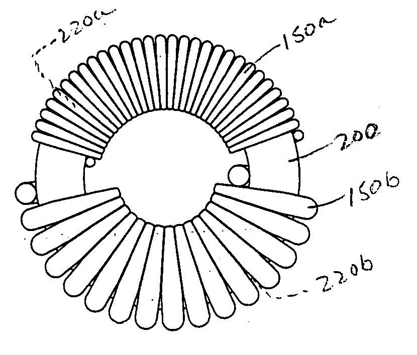
[0036] The magnetic core 200 (ref...


PUM

PropertyMeasurementUnit
temperatureaaaaaaaaaa
inductanceaaaaaaaaaa
magneticaaaaaaaaaa

Abstract

The invention relates to winding wire around a magnetic core. The invention includes forming corners on the wire that align with inside corners of the magnetic core such that the wire is more tightly wound around the magnetic core. The invention also includes pinching a portion of wire that is positioned on the internal diameter of a magnetic core when the wire is wound around the core to provide more turns of the wire around the magnetic core. A magnetic inductor made in accordance with the present invention can have increased inductance, lower temperature rise, smaller size, and exhibit less EMI noise than the prior art.

Description

FIELD OF THE INVENTION [0001] The present invention relates to winding wire on a magnetic core and to apparatuses used to wind the wire around the magnetic core, and related to transformers and inductors produced from the same. BACKGROUND OF THE INVENTION [0002] Prior U.S. patents of magnetic core winders, which include but are not limited to toroidal winders, include U.S. Pat. Nos. 5,331,729; 4,379,527; 4,872,618; 6,557,793; 4,288,041; and 5,875,988. In general, the prior art, as shown in FIGS. 1 through 3, illustrate the principle of winding magnet wire on a magnetic core (hereinafter “core”) to create an inductor. The prior art uses a supply ring 10 and winding ring 20 with pullout or open / close type ring openings 12 and 22 to enable a core 30 to be arranged with the rings 10 and 20 passing through the center hole of the core 30. In the prior art the openings 12 and 22 are opened manually and the core 30 is passed through the openings so that each ring passes through the center h...

Claims


Application Information

Patent Timeline
Patent Type & Authority Applications(United States)
IPC IPC(8): B65H81/02H01F41/08H02K1/00H02K15/08H05K
CPCH01F41/0691H02K15/08H01F41/08H01F41/077
Inventor SWEENEY, MATTHEWMEDEMA, JOHN E.ROEBER, MICHAEL G.
Owner HUBBELL INC
Why Eureka
Try Eureka