Current measuring device

a current measuring device and current measurement technology, applied in the direction of measurement devices, electrical testing, instruments, etc., can solve the problems reducing the number of components and and reducing the size of the photocircuit. , the effect of reducing the size of the photocircui

Inactive Publication Date: 2005-04-21
ADAMANT IND +1
View PDF3 Cites 26 Cited by
  • Summary
  • Abstract
  • Description
  • Claims
  • Application Information

AI Technical Summary

Benefits of technology

[0022] In the current measuring apparatus of the above arrangement, the light can be introduced into a core portion of each optical fiber through one end thereof provided in the vicinity of the birefringent member. Therefore, in contrast with conventional techniques, it is unnecessary to provide a lens between one end of each optical fiber and the birefringent member, so that the light can be introduced into the optical fibers using at least one lens. Therefore, a reduction in size of the current measuring apparatus can be achieved.
[0024] With this arrangement, the focal points of the lens system disposed between the input end of the optical fiber sensor and the birefringent member are formed at the end-face core portion of the optical fiber sensor and the end-face core portion of the first optical fiber for directing the linearly polarized light to the birefringent member while transmitting the ordinary ray from the birefringent member to the photoelectric converter. Therefore, only one lens system is required, so the number of components and the size of the photocircuit can be reduced. Further, an alignment operation becomes easy.
[0025] Further, in the arrangement where no lenses are provided between the birefringent member and the first and second optical fibers, if the thickness of the birefringent member is reduced, and therefore the separation distance between the ordinary and extraordinary rays is reduced, the distance between the first optical fiber and the second optical fiber can be matched to the separation distance. Therefore, the size of the photocircuit can be further reduced by reducing the thickness of the birefringent member.

Problems solved by technology

However, this current measuring apparatus is technically disadvantageous as explained below.
With this arrangement, however, a separation distance between the ordinary ray and the extraordinary ray emerging from the birefringent member 4 is relatively narrow, so it is extremely difficult to provide two lenses 7 between the birefringent member 4 and the optical fibers 5 and 6 in a parallel relationship.
Further, the structure shown in FIG. 11 requires a large number of components, which complicates the structure.
Aligning the lenses 7 and the optical fibers is time-consuming, and a large number of operations are required for assembly, which results in a high cost of manufacture.
However, the structure of this apparatus does not allow an operation for assembly such that the polarization preserving optical fiber 5 and the optical fiber 6 are fixed relative to each other to thereby form a subassembly, and connected to the lenses.
Therefore, the structure of the lens 9 becomes complicated and delicate adjustment is required, thus making it difficult to obtain a desired effect.
However, it is impossible to compensate for a variation in the measured value of the current due to the temperature characteristic of a 22.5° Faraday element which is disposed in the current detection unit.
Thus, there is no means to provide an inexpensive current measuring apparatus which comprises a small-size current detection unit and which efficiently receives the light to be measured that is emitted from the current detection unit, while compensating for a variation in the measured value of the current due to the temperature characteristic of the 22.5° Faraday element.
Consequently, an entire structure of the current measuring apparatus is large.

Method used


Image

  • Current measuring device
  • Current measuring device
  • Current measuring device

Examples


first embodiment

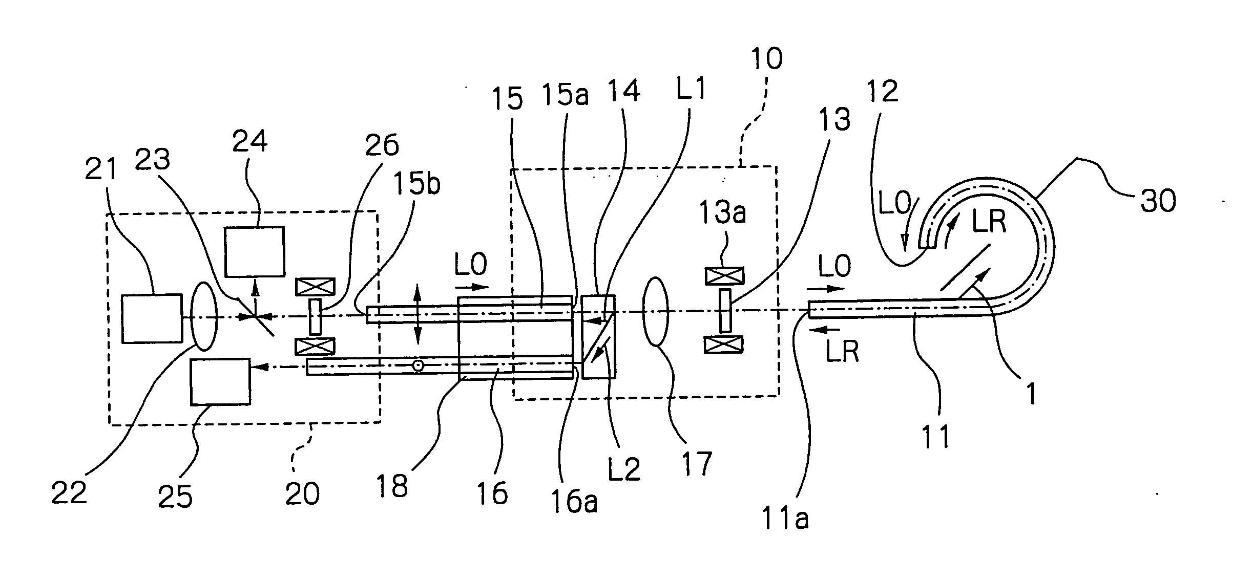
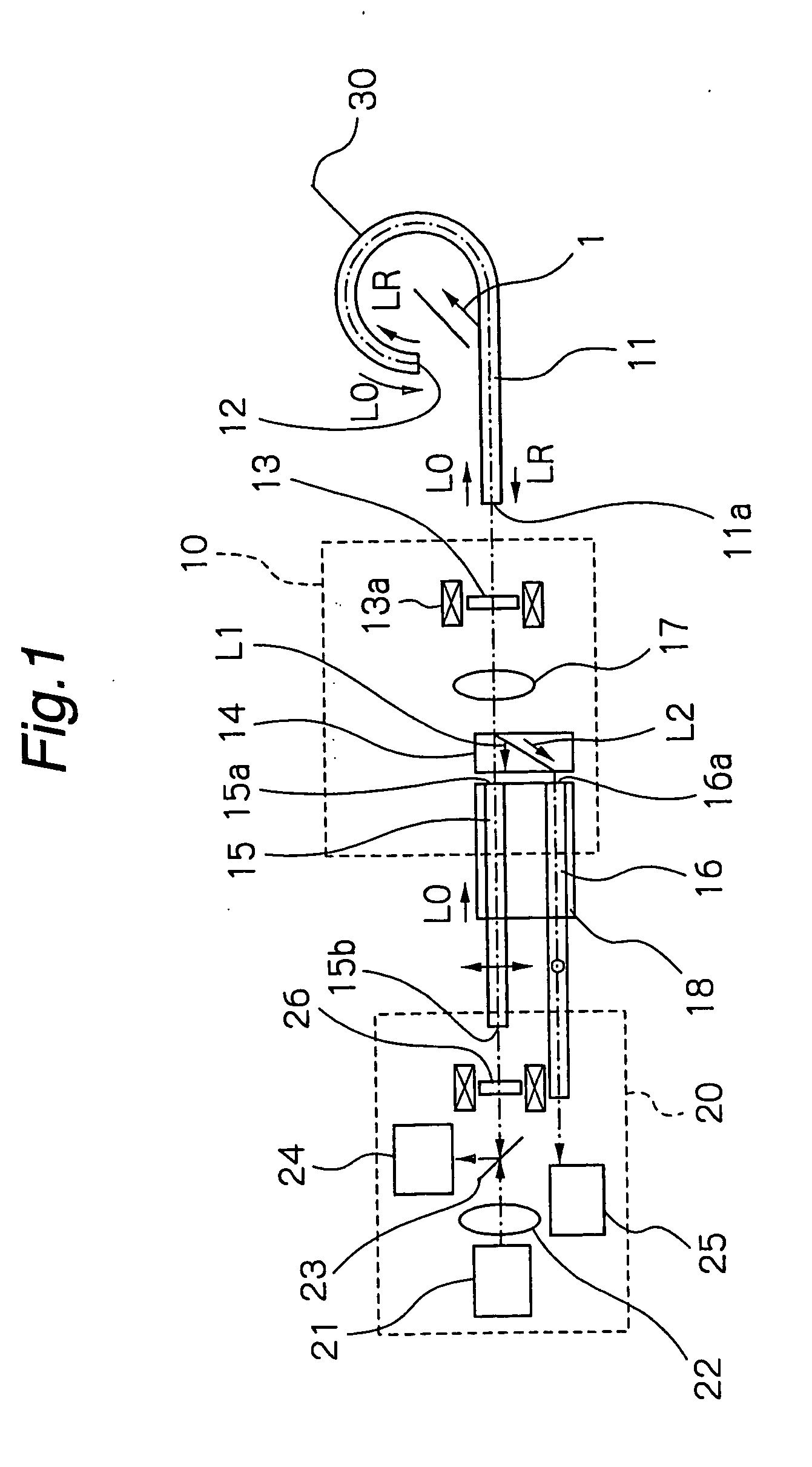
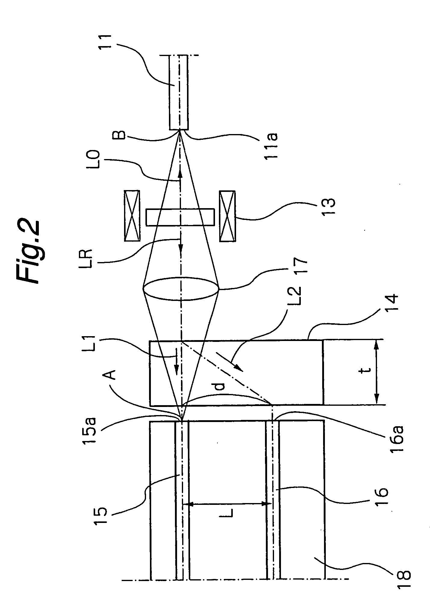
[0044] Hereinbelow, preferred embodiments of the present invention are described in detail, referring to the accompanying drawings. FIGS. 1 and 2 show a current measuring apparatus according to the present invention. The current measuring apparatus shown in FIGS. 1 and 2 comprises a reflection type optical fiber sensor 11, a photocircuit 10 and a photoelectric converter 20.

[0045] The optical fiber sensor 11 is extended or looped around a conductor 30 through which a current I to be measured flows. The optical fiber sensor 11 comprises a flint glass fiber or a silica glass fiber, through which incident linearly polarized light L0 or reflected linearly polarized light LR is propagated. A reflective film 12 as a reflecting member is provided at one end of the optical fiber sensor 11 so as to reflect the linearly polarized light L0 which has traveled in an optical path encircling the conductor 30. Although the reflective film 12 is provided in this embodiment, this does not limit the pr...

third embodiment

[0096] In the third embodiment arranged as mentioned above, the photocircuit 10 and the photoelectric converter 20a have the advantage of having similar components, which means that the components of the apparatus are less diversified. This provides the added advantage of ease of assembly when forming the components into a unit.

[0097] It should be noted that the angle of Faraday rotation in the first Faraday element 13′ in the photoelectric converter 20a shown in FIG. 4 is 45°, and the angle of Faraday rotation in the first Faraday element 13 of the photocircuit 10 in FIG. 4 is 22.5°.

fourth embodiment

[0098] Next, referring to FIG. 5, a current measuring apparatus is described.

[0099] In the current measuring apparatus in the fourth embodiment, measurement is made with respect to an angle of rotation of linearly polarized light in a current detection optical fiber sensor 102, which is caused by the Faraday effect under a magnetic field produced by a current flowing through a conductor 100. This current measuring apparatus comprises the optical fiber sensor 102 for detecting a current flowing through the conductor 100, a photocircuit 104, a photoelectric converter 106 for converting an optical value from the photocircuit 104 into an electrical value and optical fibers 108, 110 and 112 for connecting the photocircuit 104 and the photoelectric converter 106. The photocircuit 104 is a circuit for inputting, to the optical fiber sensor 11, linearly polarized light obtained from the linearly polarized light or randomly polarized light emitted from a light source 114. It is also adapted...


PUM


Abstract

A current measuring apparatus comprises a current detection unit 10 and a photoelectric converter 20. The current detection unit 10 comprises an optical fiber sensor 11 extended or looped around a conductor 30. A reflective film 12 is attached to one end of the sensor 11 so that light can be reflected by the end of the sensor. The current detection unit 10 further comprises a first Faraday element 13, a light-transmitting birefringent member 14, a first optical fiber 15, a second optical fiber 16 and a lens 17. The Faraday element 13 rotates a plane of polarization of the incident light through about 22.5°. The birefringent member 14 functions to separate the light emitted from the sensor 11 into an ordinary ray L1 and an extraordinary ray L2 that are orthogonal to each other, and to transmit linearly polarized light L0 emitted from a light source. The lens 17 is provided between the element 13 and the birefringent member 14. Focal points of the lens are formed at core portions of an input end 11a of the sensor 11 and an end face 15a of the first optical fiber 15. With this arrangement, the number of components is reduced and the apparatus is reduced in size.

Description

TECHNICAL FIELD [0001] The present invention relates to a current measuring apparatus using the Faraday effect. Specifically, the present invention relates to a current measuring apparatus using a reflection type or a transmission type optical fiber sensor. TECHNICAL BACKGROUND [0002] There is known a current measuring apparatus using the Faraday effect by which a plane of polarization of light rotates due to the action of a magnetic field. As examples of current measuring apparatuses of this type, reflection type current measuring apparatuses are disclosed in Japanese Patent Application Public Disclosure No. H10-319051 and Japanese Patent Application Public Disclosure No. 2000-292459. [0003] This type of current measuring apparatus is advantageous in that it is not affected by electromagnetic noise, and detects only a current flowing through a portion of a conductor encircled with an optical fiber, and is not affected by a current in a portion of the conductor outside the optical f...

Claims


Application Information

Patent Timeline
Patent Type & Authority Applications(United States)
IPC IPC(8): G01R15/24
CPCG01R15/246
Inventor KUROSAWA, KIYOSHIHIROKI, YOSHIHARUKONNO, YOSHIHIROSASAKI, MASARU
Owner ADAMANT IND
Why Eureka
Try Eureka