
Method and system for fast wake-up of oscillators

Inactive Publication Date: 2005-04-21
VISHAY ADVANCED TECH LTD
View PDF4 Cites 16 Cited by
  • Summary
  • Abstract
  • Description
  • Claims
  • Application Information

AI Technical Summary

Benefits of technology

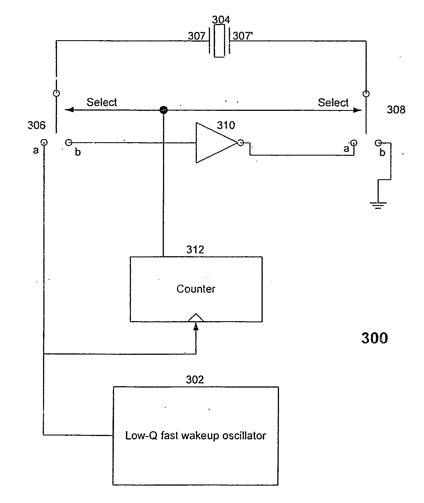
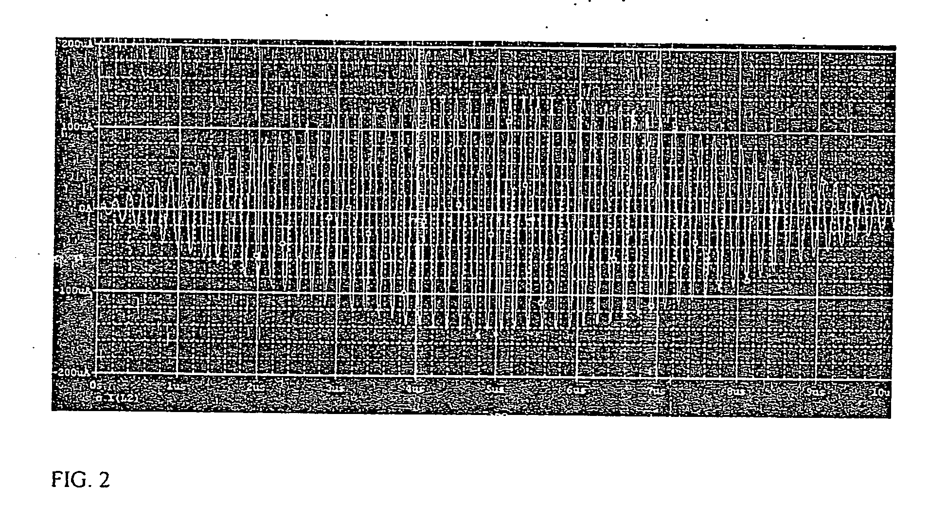
[0007] The present invention provides a method and system that uses multiple pulses to fast wakeup an oscillator but avoids the cancellation oscillations of FIG. 2. In the present invention, we can amplify and resonate an interrogating effect by applying a series of pulses, which are well timed to build an oscillating effect, therefore achieving a wake-up time far shorter than the one achieved by single “kick” pulses as in Yin and Prado above.
[0008] According to the present invention there is provided a method for reducing the start-up time of a high-Q oscillator comprising the steps of: providing a low-Q fast wake-up oscillator; providing a high-Q resonator connectable through two, first and second switches to two connecting configurations, the first of the connecting configurations connecting the high-Q resonator to the low-Q fast wake-up oscillator and to a voltage reference, and the second of the connecting configurations disconnecting the high-Q resonator from the low-Q fast wake-up oscillator; and operating the low-Q fast wake-up oscillator to generate steady state, substantially constant amplitude oscillations in the high-Q resonator when the high-Q resonator is connected in the second connecting configuration.
[0010] According to the present invention there is provided a system for fast waking up a high-Q oscillator having a resonating element connected to an internal amplifier, the system comprising: a low-Q oscillator connectable to the resonating element and operative to input a plurality of pulses to the resonating element when the resonating element is disconnected from the internal amplifier, the pulses building up the energy of the resonating element; and means to simultaneously disconnect the resonating element from the low-Q oscillator and to reconnect the resonating element to the internal amplifier, whereby the high-Q oscillator is speedily woken up by the built up energy.
[0011] According to the present invention there is provided a method for fast wakeup of a high-Q oscillator that includes a resonating element and an amplifier, the method comprising the steps of connecting the resonating element to a fast wakeup, low-Q oscillator; inputting a plurality of pulses generated by the low-Q oscillator into the resonating element, thereby building up a resonating element energy; and simultaneously disconnecting the resonating element from the low-Q oscillator while connecting the resonating element to the amplifier, thereby obtaining substantially uniform steady state oscillations in the high-Q oscillator.
[0012] Because the wakeup of the high-Q oscillator in the present invention is based on a train of pulses of equal frequency and amplitude generated by the low-Q oscillator and not on white noise, the wakeup is much more efficient and much faster than in prior art systems. Thus, the system and method of the present invention advantageously save energy in the many cases where a high-Q oscillator is active for only a very small portion of a duty cycle, because much less energy is wasted on the wakeup itself relative to the other active functions of the high-Q oscillator.

Problems solved by technology

However, this strategy has a problem in that the wake-up time of the device's oscillator could be quite long, i.e. several microseconds.
This makes such a strategy unattractive.
Because this signal is very small, one needs to wait a long time for the energy in the resonator to build lip.
However, both Yin's and Prado's use of a single “kick” pulse has a major disadvantage: it provides a wake-up time that is still far too long in comparison with the times achievable with the method and system of the present invention, i.e. wastes energy.
By providing a single interrogating pulse to the crystal resonator, one does not fully utilize the potential of awakening the crystal oscillator in a fast and efficient manner.

Method used


Image

  • Method and system for fast wake-up of oscillators
  • Method and system for fast wake-up of oscillators
  • Method and system for fast wake-up of oscillators

Examples


Embodiment Construction

[0019] The system and method of the present invention provide a finite, optimal number (“train”) of pulses for optimal wakeup time. The optimal number of pulses is mostly defined by the accuracy of the fast wakeup RC oscillator used to interrogate the crystal. The more accurate it is, the higher the number of pluses one can feed to the crystal without destroying the energy already accumulated.

[0020] As mentioned above, fast wake-up oscillators have been implemented that use a single pulse from a source to “kick-start” the oscillations. There are no known methods or circuits that use intentionally introduce multiple pulses (not “white noise”) that aim to achieve the same effect. Thus, the intentional use of multiple, substantially equal pulses to fast wakeup a high-Q oscillator, as disclosed herein, is by itself innovative. However, a simplistic use of multiple pulses may not lead to the required result. Specifically, if the frequency of a train of pulses is offset from the resonati...


PUM


Abstract

A method and system for fast wakeup of a high-Q oscillator (300) that includes a resonating element (304), preferably a crystal resonator (304), and an amplifier (310). The method comprises connecting the resonating element (304) to a fast wakeup, low-Q oscillator (302), inputting a plurality of pulses generated by the low-Q oscillator (302) into the resonating element (304), and simultaneously disconnecting the resonating element (304) from the low-Q oscillator (302) while connecting the resonating element (304) to the amplifier (310), thereby obtaining substantially uniform steady state oscillations in the high-Q oscillator. The system (300) includes in addition to high-Q and low-Q oscillator elements a mechanism for counting the pulses (312) and for performing the simultaneous disconnection and connection mentioned above.

Description

CROSS-REFERENCE TO RELATED APPLICATIONS [0001] This application is entitled to the benefit of priority from U.S. Provisional Application No. 60 / 418,339 filed Oct. 16, 2002.FIELD OF THE INVENTION [0002] The present invention relates generally to crystal oscillators, and more particularly, to oscillators with fast start times. BACKGROUND OF THE INVENTION [0003] Many consumer products in use today have embedded RF wireless communication elements. Wireless consumer products ideally require low power consumption and low cost. One strategy for low power consumption (i.e. power conservation) in low data rate applications is to use a device that normally includes at least one oscillator in a mode of bursts of very high rate data streams, separated by “sleep” modes during which the device consumes very little current. However, this strategy has a problem in that the wake-up time of the device's oscillator could be quite long, i.e. several microseconds. This makes such a strategy unattractive...

Claims


Application Information

Patent Timeline
IPC IPC(8): H03B1/00H03B5/06H03B5/36
CPCH03B5/36H03B5/06
Inventor GAZIT, MEIR
Owner VISHAY ADVANCED TECH LTD
Learn More