Gradient liquid feed pump system, and liquid chromatograph

a pump system and gradient liquid technology, applied in the direction of pump parameters, positive displacement liquid engines, instruments, etc., can solve the problems of difficult to execute liquid feed at a stable pressure, difficult to correctly predict the time band in which pressure interference occurs,

Inactive Publication Date: 2005-04-21
HITACHI HIGH-TECH CORP +1
View PDF2 Cites 27 Cited by
  • Summary
  • Abstract
  • Description
  • Claims
  • Application Information

AI Technical Summary

Benefits of technology

[0008] It is therefore an object of the invention to provide a gradient liquid feed pump system capable of liquid feed at a correct mixing ratio by reducing the effect of pressure interference even in the case of flow rates in respective pumps varying by the moment, and a liquid chromatograph using the gradient liquid feed pump system.
[0010] As a result, it becomes possible to execute the liquid feed at a stable mixing ratio of the eluants.

Problems solved by technology

With the pump system using the plunger pumps, pressure drop causing the pressure interference occurs in a time period during which the plunger pump having check valves undergo transition from a suction interval to a delivery interval.
In the case of flow rates in the respective plunger pumps varying by the moment, the time period during which the pressure interference occurs vary by the plunger pump, so that it is difficult to correctly predict a time band in which the pressure interference occurs.
For this reason, there have been cases where the delivery pressure is found too high or too low, depending on timing for completing the high-speed operation of the motor, so that it has been impossible to execute the liquid feed at a stable pressure.

Method used


Image

  • Gradient liquid feed pump system, and liquid chromatograph
  • Gradient liquid feed pump system, and liquid chromatograph
  • Gradient liquid feed pump system, and liquid chromatograph

Examples


Embodiment Construction

[0020] Embodiments of the invention are described hereinafter.

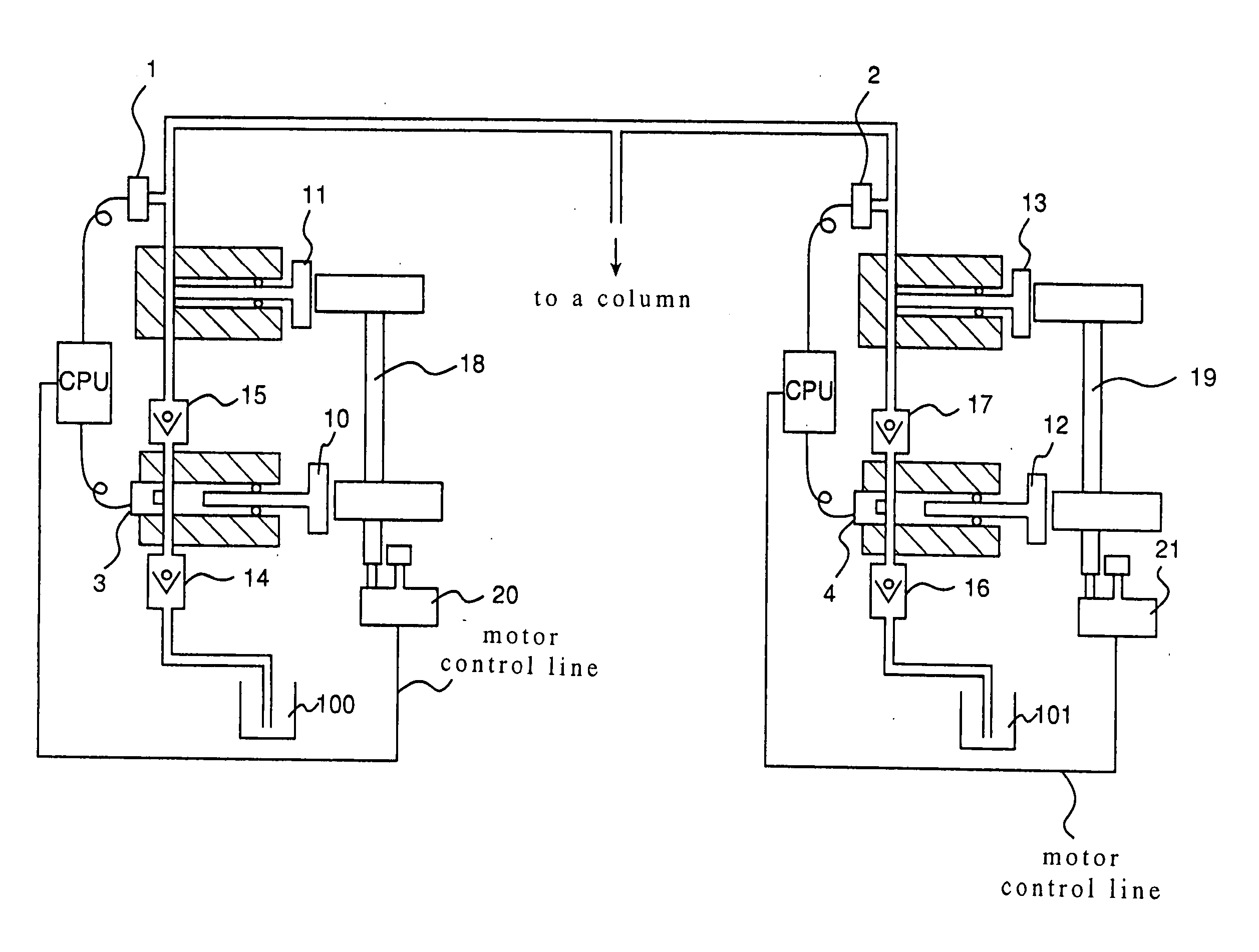
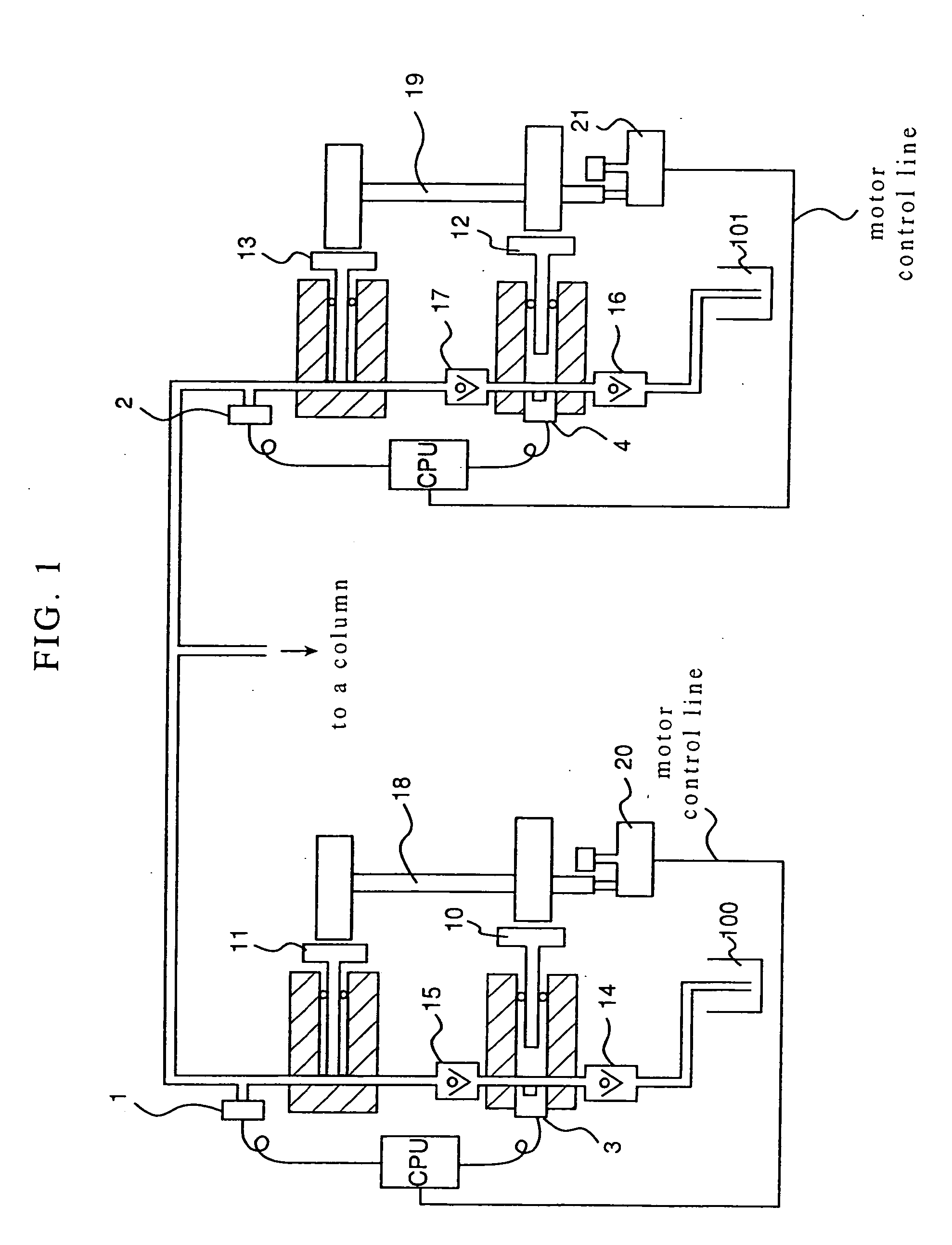
[0021]FIG. 1 is a schematic block diagram of an embodiment of a high-pressure gradient elution pump system according to the invention, comprising two units of pumps. The respective pumps are provided with two pump chambers, and motors (preferably, pulse motors) 20, 21 drive respective pistons of the pump chambers through cams 18, 19, respectively. The pump chambers on the sides of the respective pumps, adjacent to eluants 100, 101, respectively, are provided with a check valve for prevention of reverse flow, on the delivery and suction sides thereof, respectively, and liquid feed is effected by first pistons 10, 12, respectively, while the pump chambers on the sides of the respective pumps, adjacent to a separation column, are not provided with a check valve, effecting liquid feed by second pistons 11, 13, respectively.

[0022] The second pistons 11, 13 each deliver liquid in an interval when the first pistons 10, 12 each...


PUM

PropertyMeasurementUnit
retention timeaaaaaaaaaa

Abstract

A gradient liquid feed pump system capable of liquid feed in a correct mixing ratio even in the case of liquid feed in which the mixing ratio varies. Specifically, it comprises a first plunger pump for sucking and delivering an eluate, a second the first and second plunger pumps through a cam, a first pressure sensor for measuring the pressure in the flow path of the second plunger pump, a second pressure sensor for measuring the pressure in the fist plunger pump, a cam position detecting sensor for detecting the cam position, wherein when the cam position is in a delivery interval, the rotary speed of the motor is increased, and the period for decreasing the rotary speed is determined on the basis of the difference between the pressure values obtained from the first and second pressure sensors, respectively. Thereby, liquid feed can be smoothly effected with correct mixing ratio while avoiding pressure interference between pumps.

Description

TECHNICAL FIELD [0001] The present invention relates to a pump for executing gradient liquid feed, and in particular to a pump for use in a liquid chromatograph for executing high-pressure gradient liquid feed. BACKGROUND ART [0002] With a high-pressure gradient liquid chromatograph for executing analysis while varying a mixing ratio of eluants fed into a separation column, a plurality of the eluants are fed by different pumps, respectively. In the case of using a plunger pump provided with check valves, executing liquid feed by the reciprocating motion of a piston, for each of the pumps, there occurs time periods when pressure drop develops on the side of one of the pumps, adjacent to the separation column, (on the delivery side of the pump), due to the constitution thereof. Such pressure drop is introduced to the liquid feed of the other pump, resulting in so-called pressure interference between the pumps, so that the liquid feed at a flow rate according to a program is hindered, ...

Claims


Application Information

Patent Timeline
Patent Type & Authority Applications(United States)
IPC IPC(8): F04B11/00F04B13/02G01N30/32G01N30/34
CPCF04B11/0075F04B13/02F04B2201/1201G01N2030/326F04B2205/05G01N30/32G01N30/34F04B2201/1208
Inventor MORI, KIYOTOSHITAKAHASHI, KENICHIROTAKAKI, MASANORIFUKUDA, MASATOITO, MASAHITOKAJI, HIRONORI
Owner HITACHI HIGH-TECH CORP
Why Eureka
Try Eureka