Portable laser device

a laser device and portability technology, applied in the field of portability laser devices, can solve the problems of reducing the efficiency increasing the temperature of the laser rod, and wasting a large portion of the optical radiation of the exciting lamp which passes through the laser rod, and achieve the effect of facilitating heat removal

Inactive Publication Date: 2005-04-21
INNOTECH USA
View PDF12 Cites 51 Cited by
  • Summary
  • Abstract
  • Description
  • Claims
  • Application Information

AI Technical Summary

Benefits of technology

[0012] As to another embodiment of the invention, at least one connecting element for communication between the housing and the intermediate accumulation chamber is provided. A pumping arrangement is associated with the connecting element, so as to provide circulation of a liquid coolant between the housing and the intermediate accumulation chamber. A buffer space is formed between the exterior and interior walls of the casing. The buffer space communicates with the intermediate accumulation chamber. The exterior of the housing and intermediate accumulation chamber are situated within the stream of gaseous coolant, so as to facilitate heat removal from the liquid coolant contained thereinside. A plurality of cooling fins are formed of a heat conducting material and extend from the inner wall of the casing. The plurality of cooling fins are positioned within the stream of gaseous coolant for heat removal from the liquid coolant situated within the buffer space.

Problems solved by technology

Therefore, a considerable portion of the exciting lamp optical radiation which passes through the laser rod is wasted by converting into a useless thermal energy.
As a result, when the exciting lamp constantly pulses its radiation in the direction of the laser rod to generate a required laser output beam, the temperature of the laser rod rises, diminishing its efficiency.
Thus, development of effective, miniature cooling arrangements adapted for the removal of thermal energy from the laser rod assemblies is considered to be a key problem in the development of hand-held laser devices.
On the other hand, use of the liquid coolants does not provide the long-term stability of the optical medium, and often leads to contamination of the optical surfaces of the laser rod, exciting lamp and reflector.
Furthermore, the currently available liquid cooling arrangements substantially increase weight and dimensions of the respective laser devices.
However, utilization of the liquid cooling for the cooling of the laser rods and the exciting lamps increases the dimensions of the laser emitter, as well as brings up many other problems associated with the liquid cooling discussed hereinabove.
One of the major drawbacks of this arrangement is that the heat removal from the laser rod is carried out indirectly through cooling of the exterior of the entire laser cavity.
This approach substantially diminishes the efficiency of the laser assembly cooling process.

Method used


Image

  • Portable laser device
  • Portable laser device
  • Portable laser device

Examples


Embodiment Construction

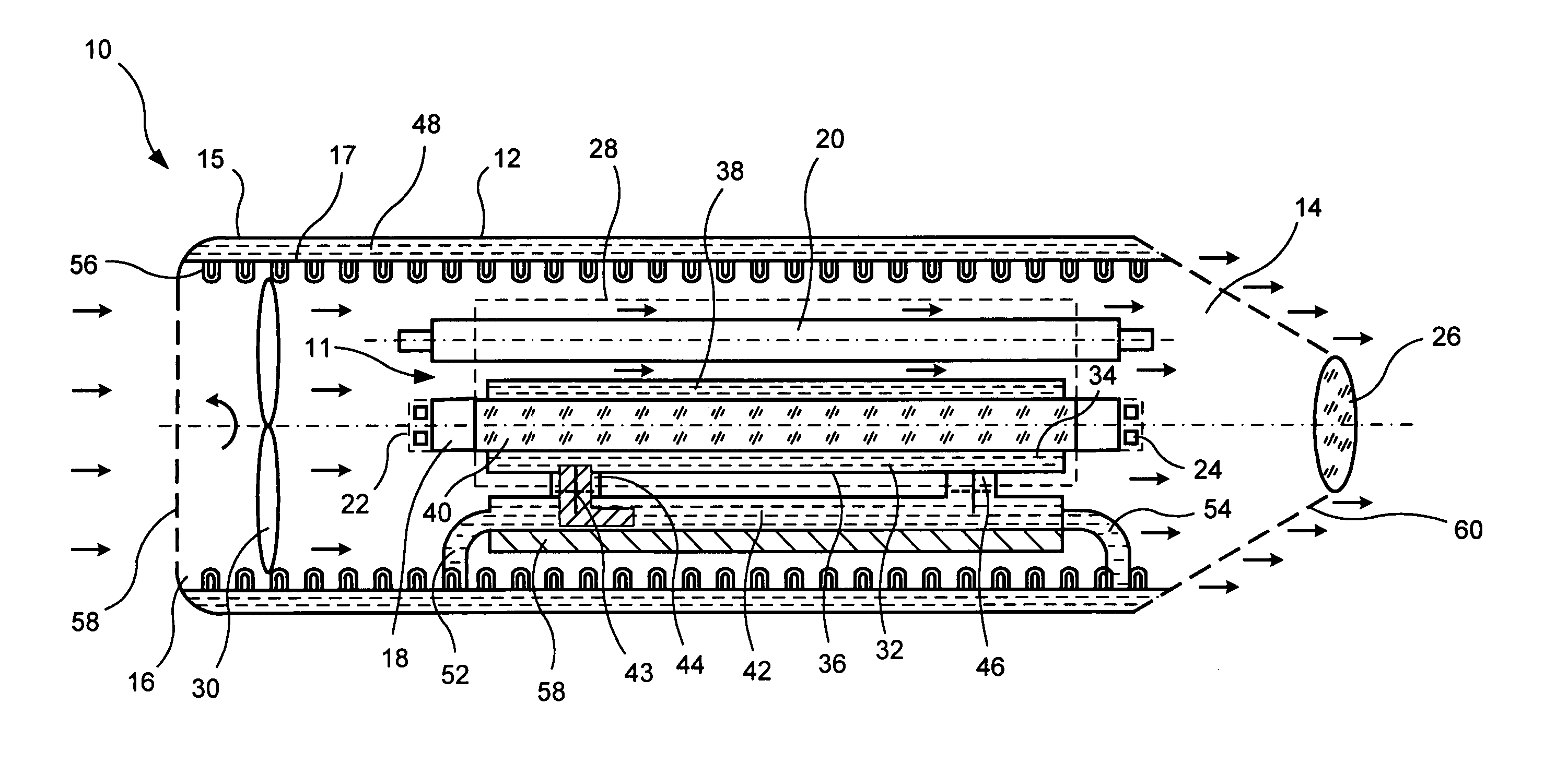
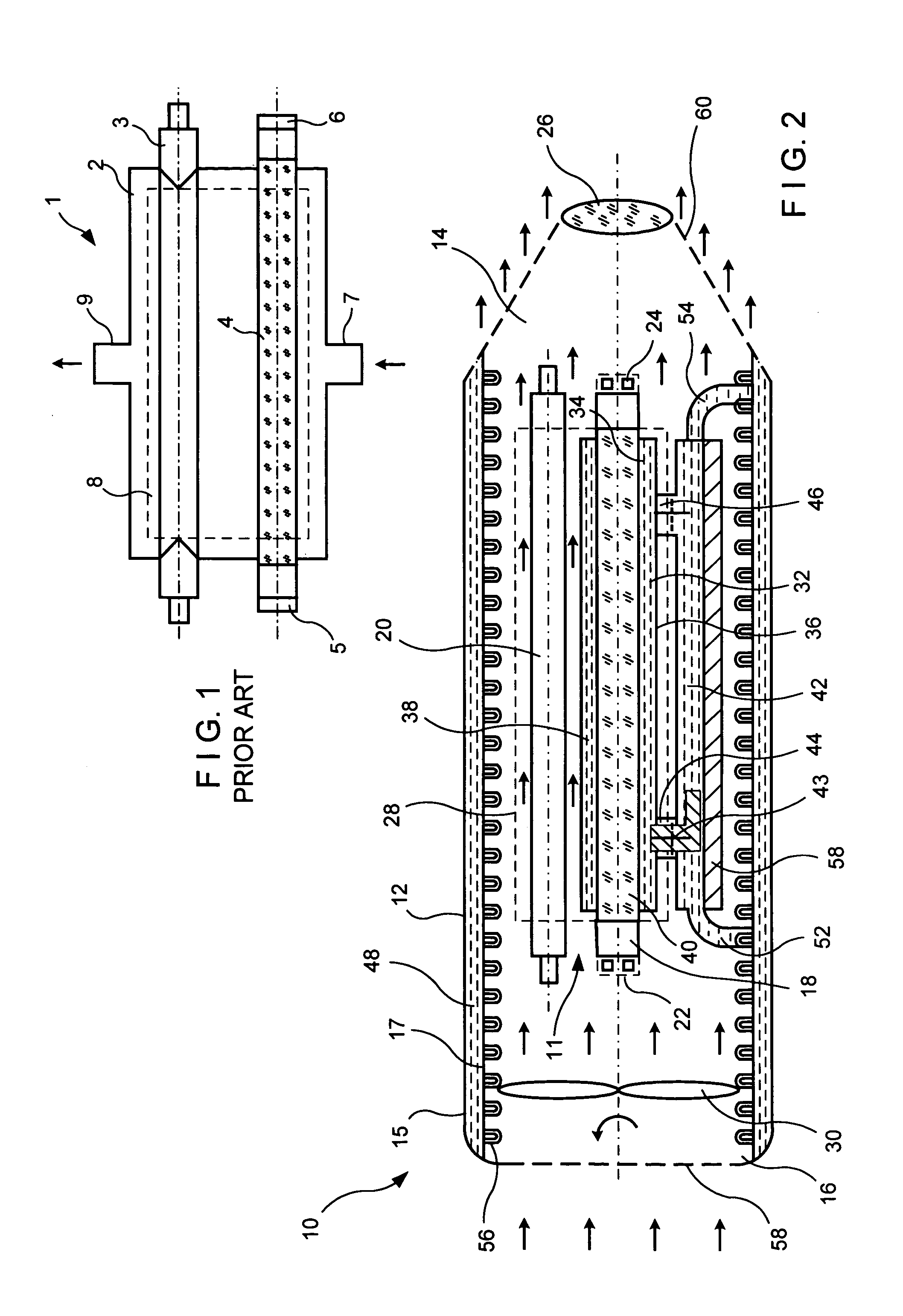
[0027] Referring now to FIG. 2, illustrating one embodiment of a portable, hand-held laser device 10 having a laser emitter 11 disposed in a substantially hollow, elongated casing 12 which extends longitudinally between front 14 and rear 16 ends thereof. The casing is formed by exterior 15 and interior 17 walls defining a buffer space 48 therebetween. We shall revert to this structure later on in the application. Within an interior of the casing a laser rod 18 is disposed substantially centrally with an exciting lamp 20 being spaced therefrom. A fully-reflective or rear resonant mirror 22 is positioned at a rear end of the laser rod and at an optical axis thereof. An output or front resonant mirror 24 is situated in front of the laser rod at an optical axis thereof. A laser beam forming arrangement or focusing lens 26 is housed at the front end 14, so that the output mirror 24 is interposed between the laser rod 18 and the lens 26. To facilitate passage of the laser beam the output ...


PUM


Abstract

A hand-held laser device includes a casing formed with a substantially hollow interior space and having a laser emitter thereinside. The laser emitter is formed with an exciting lamp and a laser rod. A source generating a stream of gaseous coolant is provided within the interior space. A fluid cooling arrangement at least partially surrounding the laser rod is disposed within the stream of gaseous coolant for heat removal therefrom.

Description

[0001] This non-provisional application claims benefit under 35 USC 119(e) of U.S. Provisional application Ser. No. 60 / 307,628 filed by Valentin A. Gruzdev and Pavel V. Efremkin on Jul. 25, 2001.BACKGROUND OF THE INVENTION [0002] 1. Field of the Invention [0003] The invention relates in general to portable laser devices based on a solid-state laser technology, and in particular it relates to hand-held laser devices with direct cooling of a laser rod assembly. [0004] 2. Discussion of Background and Prior Art [0005] The laser radiation generated by solid-state lasers is widely used in the industry and medicine. As illustrated in FIG. 1 a typical laser emitted assembly consists of a laser rod 6, an exciting lamp 3, a reflector 8, a pair of resonant mirrors 5, 6 and a cooling arrangement 7, 9. The wavelength of a laser radiation is determined by the type of a laser rod. The duration of the laser impulse and its energy are primarily set by the power source associated with the laser devic...

Claims


Application Information

Patent Timeline
Patent Type & Authority Applications(United States)
IPC IPC(8): H01S1/00A61B18/00A61B18/20H01S3/02H01S3/04
CPCA61B18/20A61B2018/00017A61B2018/00023A61B2018/202H01S3/02H01S3/0931H01S3/0404H01S3/0407H01S3/042H01S3/061H01S3/093H01S3/025
Inventor GRUZDEV, VALENTIN A.EFREMKIN, PAVEL V.
Owner INNOTECH USA
Why Eureka
Try Eureka