Scalable, fault tolerant notification method

a notification method and fault-tolerant technology, applied in data switching networks, special service provisioning for substations, digital transmission, etc., can solve problems such as not providing support for application-specific routing

Inactive Publication Date: 2005-04-21
MICROSOFT TECH LICENSING LLC
View PDF13 Cites 127 Cited by
  • Summary
  • Abstract
  • Description
  • Claims
  • Application Information

AI Technical Summary

Benefits of technology

[0010] In accordance with the invention, a multicasting infrastructure incorporates the path locality infrastructure of an overlay network to realize multicast dissemination trees that may reside either within a single administrative domain or may span multiple administrative domains. This multicasting infrastructure also provides for multicast dissemi

Problems solved by technology

However, the generic routing protocols of the Internet (e.g. Internet Protocol or “IP” routing) do not provide

Method used


Image

  • Scalable, fault tolerant notification method
  • Scalable, fault tolerant notification method
  • Scalable, fault tolerant notification method

Examples


first embodiment

[0061] In accordance with the first embodiment, FIG. 3 depicts a set of nodes in an overlay network 300 divided into network regions, where an organization owns each network region. The multicast tree 303 includes a subset of nodes in the overlay network, wherein each node in the multicast tree 303 is located in network region 301 owned by Organization B. Because the root node 302 of multicast tree 303 is located in a network region 301 owned by Organization B, Organization B is said to own the multicast tree 303. Furthermore, each node in the overlay network 300 has a node name 205. FIG. 2d shows that a node name 205 comprises an organizational prefix 211 and an organization-relative suffix 212. The organization-relative suffix 212 can encode a geographic locality within an organization, thereby constraining the multicast dissemination tree to a network region within the network region of the organization.

[0062] An embodiment of the invention provides a feature that prohibits nodes...

second embodiment

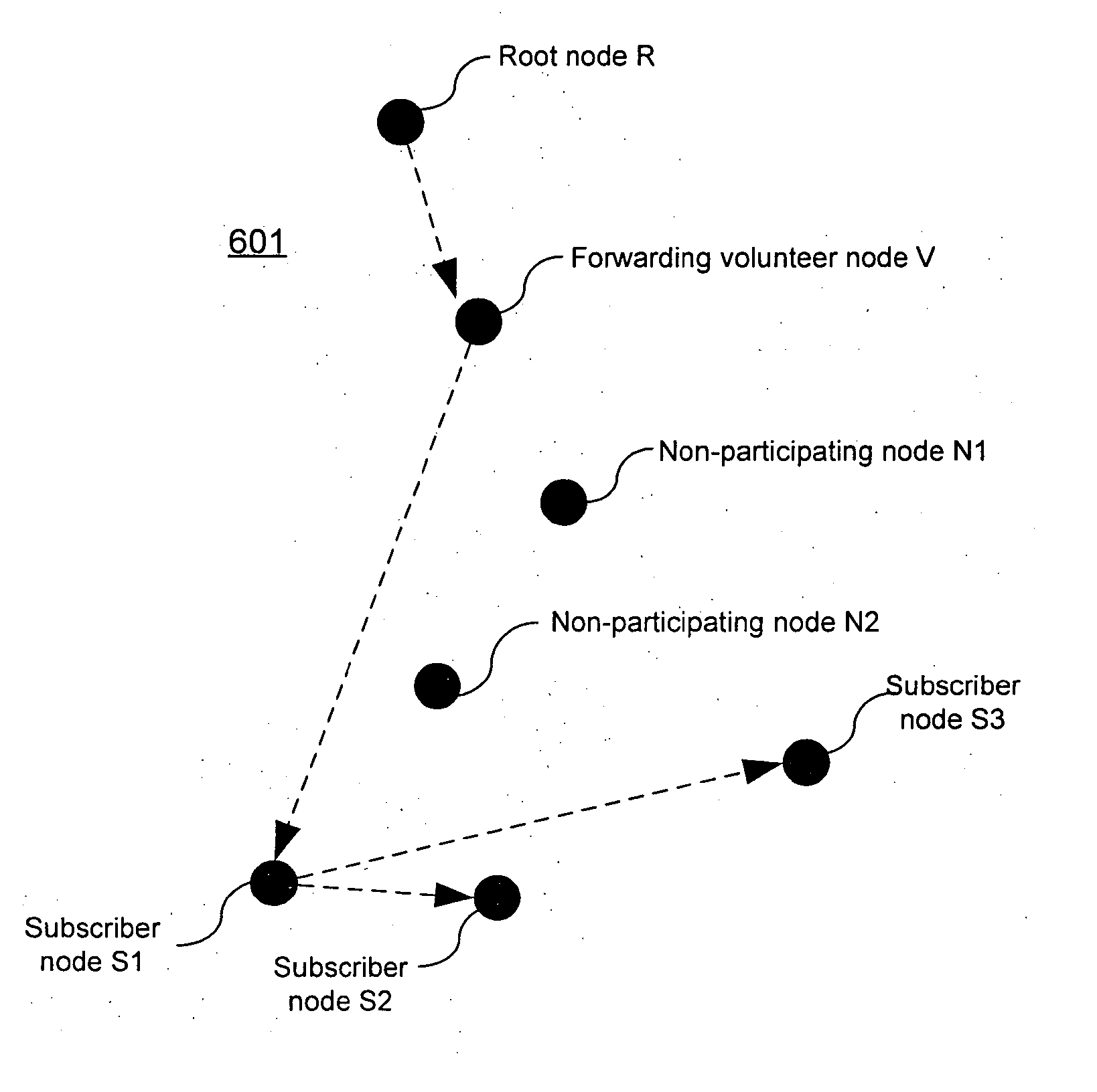
[0079] The present invention derives an SV tree from each Scribe tree it employs. This tree is comprised of all the subscriber and “volunteer” forwarding nodes in the Scribe tree. In FIG. 6b the SV tree 601 contains root node R, volunteer node V1, and subscriber nodes S1, S2, and S3. the invention employs both a Scribe tree and an associated SV tree to implement each multicast tree that it creates. The Scribe tree is the result of subscription messages that are routed by newly-subscribing overlay nodes towards the root node of a multicast tree. The Scribe tree provides a scalable way for clients to join a multicast tree. The associated SV tree is used to actually disseminate event notification messages. The SV tree provides a scalable way to forward event traffic that employs only willing participants.

[0080] An SV tree is constructed by having nodes from the associated Scribe tree that do not wish to participate in forwarding event traffic delegate their forwarding duties to some de...

third embodiment

[0102] A further embodiment of the invention employs multiple multicast trees to ensure reliable delivery of event notification messages in the face of both failed and malicious multicast tree nodes. In accordance with the third embodiment, FIG. 7 depicts a plurality of parallel multicast trees. Primary multicast tree T1 includes root node R1 and subscriber S1. Secondary multicast tree T2 includes root node R2 and subscriber S1. Secondary multicast tree T3 includes root node R3 and subscriber S1. Secondary multicast tree T4 includes root node R4 and subscriber S1. Publisher P1 sends event notification messages to each multicast tree T1-4 in parallel, and each tree delivers those messages to subscriber S1 in parallel. Thus, if there is a malicious node in primary multicast tree T1 preventing delivery to a subscriber, delivery may still occur through a parallel secondary multicast tree sharing the same subscriber. Because the cost of maintaining parallel trees is only the memory space...


PUM


Abstract

A scalable, fault-tolerant, federated event notification method is described, wherein clients express interest in a topic by subscribing, and published event notifications are delivered to all current topic-subscribers. Event notifications are disseminated by a multicast tree that does not require participation by unwilling nodes. The multicast tree is constructed so that nodes belonging to the organization owning the tree do not rely on nodes outside the organization to forward message traffic. Event notifications are delivered using redundant tree-based application-level multicast to ensure reliable delivery.

Description

TECHNICAL FIELD [0001] This invention relates generally to a multicasting infrastructure and, more particularly, to a multicasting infrastructure for providing a scalable, highly available multicasting event notification service and ensuring reliable delivery of event messages. BACKGROUND OF THE INVENTION [0002] As ever-increasing numbers of computers are networked together on the Internet, the usefulness and importance of peer-to-peer (P2P) network applications and distributed databases have become evident. A peer-to-peer network is generally thought of as a self-managed network of computers in which there is no single server or controller responsible for maintaining the network. Because there is no central server, peer-to-peer networks scale well since the load created by new members is distributed across all members of the network, rather than a central server. This scalability makes peer-to-peer networks particularly amenable to multicast applications such as event notification ...

Claims


Application Information

Patent Timeline
IPC IPC(8): H04L9/00H04L12/18
CPCH04L12/1854H04L12/1877H04L12/1859
Inventor DUNAGAN, JOHNHARVEY, NICHOLAS J.A.JONES, MICHAEL B.THEIMER, MARVIN M.WOLMAN, ALASTAIR
Owner MICROSOFT TECH LICENSING LLC
Why Eureka
Try Eureka