Optical pickup apparatus
- Summary
- Abstract
- Description
- Claims
- Application Information
AI Technical Summary
Benefits of technology
Problems solved by technology
Method used
Image

Examples
first embodiment
[0028]FIG. 6 is an exploded, perspective view showing an optical disk apparatus using an optical pickup apparatus according to the invention. In the drawing, the optical disk apparatus 1 mainly comprises an apparatus body 10, a disk tray 4 for carrying-in and carrying-out of a disk, which constitutes an information recording medium, from the apparatus, and a circuit substrate 9 mounting thereon semiconductor parts to perform control of drive of and signal processing of electronic parts provided in the optical disk apparatus 1. A top cover 2 and a front cover 3, respectively, are provided on an upper surface and a front surface of the apparatus body 10 to cover the upper and front surfaces of the apparatus body.
[0029] Mounted to the disk tray 4 is a unitary mechanism (referred below to as unit mechanism) 6, an underside of which is covered by a bottom cover 8. Mounted on the unit mechanism 6 is a spindle motor 5 for rotating a disk, a recording or reproducing, or reproducing exclusiv...
second embodiment
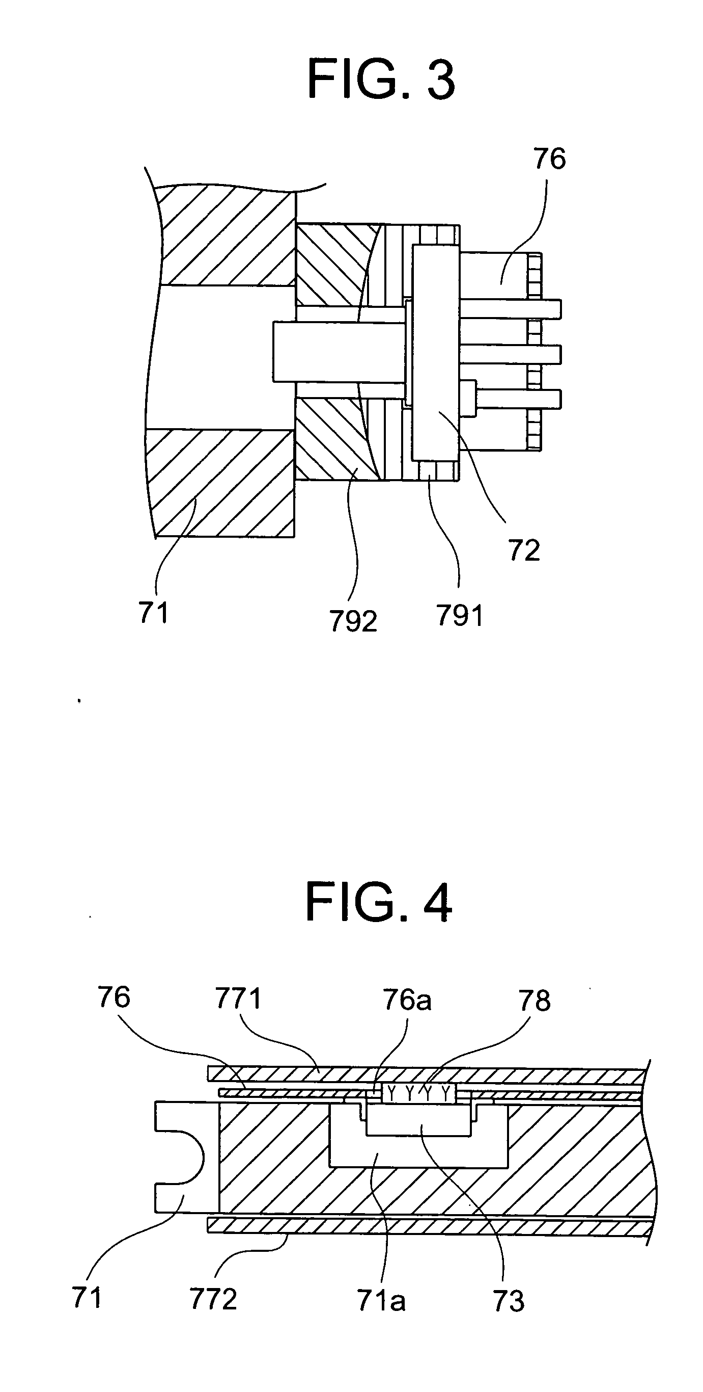
[0040] While according to the embodiment, the hole 76a is formed through the flexible substrate 76 as shown in FIG. 4 and the heat conduction member 78 is positioned in the hole 76a to achieve thermal connection of the laser driving circuit 73 and the upper cover 771, a construction shown in FIG. 8 is also possible. According to this second embodiment, opposed surfaces of both the flexible substrate 76 and the upper cover 771 are made conductive surfaces in the case where the flexible substrate 76 is interposed between the laser driving circuit 73 and the upper cover 771. A first thermal conductive member 781 connects between the conductive surface of the laser driving circuit 73 and the conductive surface of the flexible substrate 76, and a second thermal conductive member 782 connects between the flexible substrate 76 and the upper cover 771. The first thermal conductive member 781 is made of a resin material containing a metallic filler, or solder being electrically conductive. T...
third embodiment
[0041] Further, a construction shown in FIG. 9 is possible. According to this third embodiment, the lower cover 772, which is not connected to the laser driving circuit 73 in FIG. 4, is connected to the laser driving circuit 73 through a third thermal conductive member 783. The third thermal conductive member 783 is made of a resin material containing a metallic filler, a silicone resin, etc. Thereby, heat cooling paths extending from the laser driving circuit 73 can be increased, so that the laser driving circuit 73 can be restricted to be low in temperature.
[0042] As described above, according to the invention, the laser beam sources are connected to the optical pickup housing by metallic members and the laser driving circuit is connected to the upper cover or the lower cover without the medium of the optical pickup housing whereby any thermal interference is prevented from occurring between the laser beam sources and the laser driving circuit to hinder cooling of each other. Acco...
PUM
 Abstract
Description
Claims
Application Information
 - R&D
- Intellectual Property
- Life Sciences
- Materials
- Tech Scout
- Unparalleled Data Quality
- Higher Quality Content
- 60% Fewer Hallucinations
Browse by: Latest US Patents, China's latest patents, Technical Efficacy Thesaurus, Application Domain, Technology Topic, Popular Technical Reports.
© 2025 PatSnap. All rights reserved.Legal|Privacy policy|Modern Slavery Act Transparency Statement|Sitemap|About US| Contact US: help@patsnap.com