Closed cycle refrigeration system and mixed component refrigerant

a closed cycle, refrigerant technology, applied in the field of refrigeration cycles, can solve the problems of difficult to find efficient and reliable systems, difficult to maintain, and require more expensive equipment and frequent maintenan

Inactive Publication Date: 2005-04-28
ADVANCED RES SYST
View PDF15 Cites 26 Cited by
  • Summary
  • Abstract
  • Description
  • Claims
  • Application Information

AI Technical Summary

Benefits of technology

[0018]FIG. 3 is a plot of temperature against time illustrating cooldown performance of a system according to the present invention.
[0019]FIG. 4 is a plot of the data described in the operation of Example XII.

Problems solved by technology

However, when the temperatures to be achieved are in the semi-cryogenic (230° K to 120° K) or cryogenic range (below 120° K), then efficient and reliable systems are hard to find.
This problem is especially critical when temperatures below 120° K, e.g. close to liquid nitrogen condensation / boiling temperature (77° K), are to be achieved.
This in turn requires more expensive equipment and frequent maintenance.
A closed cycle refrigeration system utilized to provide relatively low temperatures, for example significantly below about 230° K, in the cryogenic range, for example about 70° K, encounters certain problems in providing an efficient system.
This type system is not practical, however, for small refrigeration systems where heat exchangers and cold heads are to be close to or need to be integrated with the system interface to be cooled.
Neither U.S. Pat. No. 5,337,572 or British Patent No. 1,336,892 teach or suggest a system or how to design a system that provides efficient long term operation, due to the problems associated with oil circulating with the mixed component refrigerant and the water vapor that the system desorbs during such long term operation.
Under these conditions a larger system will be required, thus increasing the cost of the equipment and operating costs, a significant problem in actual applications.
This complicates the system mechanically and complicates operation.
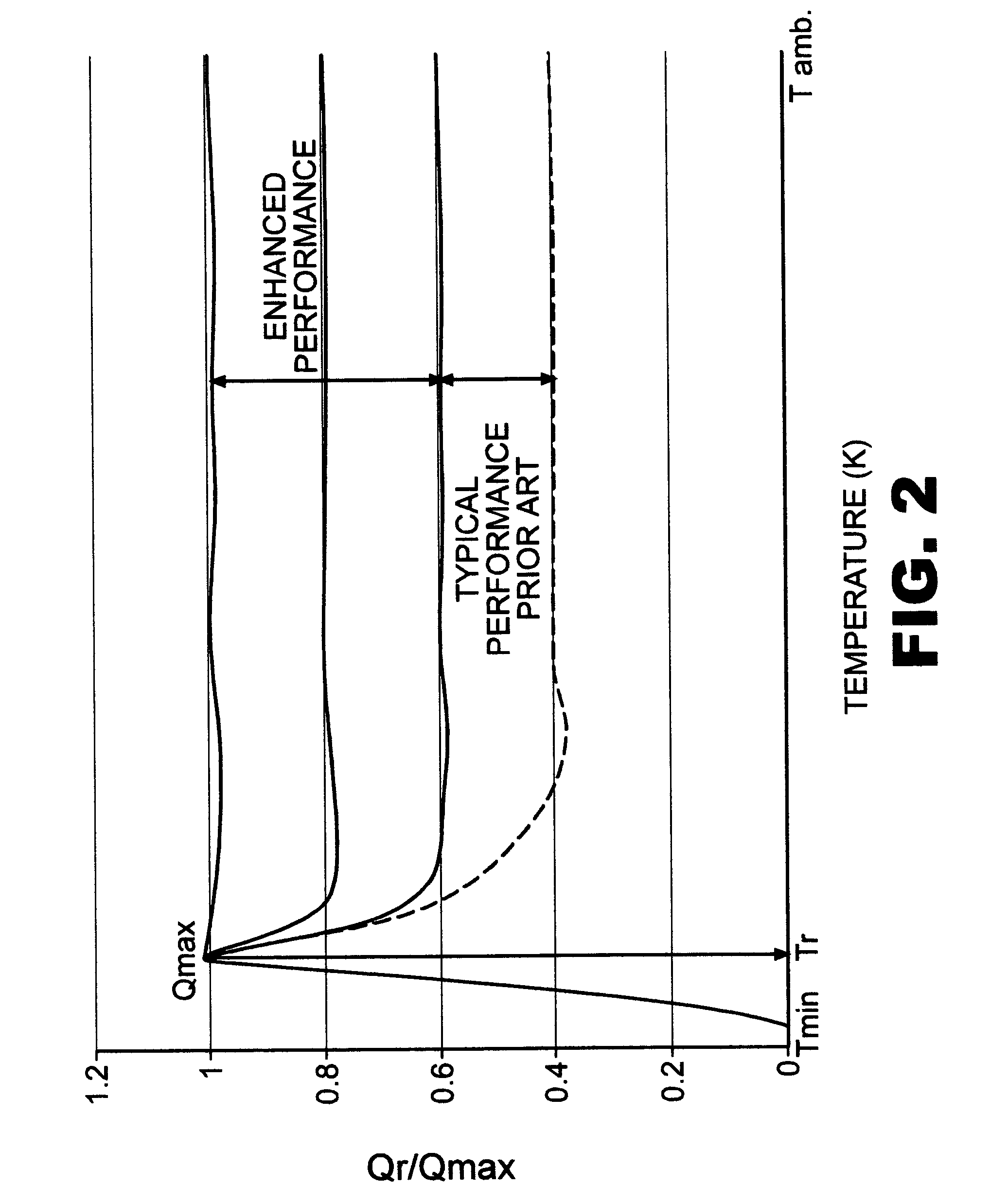
The problem related to cooldown from ambient is not fully recognized and addressed in the prior art.

Method used


Image

  • Closed cycle refrigeration system and mixed component refrigerant
  • Closed cycle refrigeration system and mixed component refrigerant
  • Closed cycle refrigeration system and mixed component refrigerant

Examples


examples

[0056] The following examples are illustrative of the operation and advantages of the present invention.

example i

[0057] In this Example a mixed component refrigerant of Table 4 would be employed in a closed cycle system of this invention utilizing a fixed sized capillary tube as the throttling device. The capillary tube would have an inside diameter of 0.030 inch and a length of 90 inches. The system thus designed would provide a refrigeration capacity during cooldown of about 65% of the maximum steady state refrigeration capacity when employing the specific mixed component refrigerant.

TABLE 4Melting (triple)Conc.ComponentMol. Wt.Boil. Pt., ° K.Pt., ° Kmol %Neon20.1827.226.915Nitrogen (N2)28.0277.363.235CF488145.289.335(R-14)C3F8188.02236.5125.515(R-218)

[0058] During operation of the system, more rapid cooldown from ambient temperature to the desired operating temperature in the cryogenic range below about 120° K would be achieved. This results in higher refrigeration capacity at steady state conditions.

[0059] Repeating this run using a capillary tube having an inside diameter of 0.016 inch...

example ii

[0060] Selecting another mixed component refrigerant such as described in Table 5 for the system of invention utilizing a fixed size orifice plate having an inside diameter of 0.032 inches as the throttling device would provide a refrigeration capacity during cooldown of about 75% of the maximum steady state refrigeration capacity when employing the (mixed component refrigerant) of Table 5.

TABLE 5Melting (triple)Conc.ComponentMol. Wt.Boil. Pt., ° K.Pt., ° Kmol %Helium44.23.610Nitrogen (N2)28.0277.363.230Argon39.9487.283.85CF487.97145.289.330(R-14)CHF370.0119111810(R-23)C3F8188.02236.5125.515(R-218)

[0061] The throttle device was selected to achieve greater than about 75% of the steady state refrigeration capacity during cooldown from ambient temperature. During operation of the system, more rapid cooldown from ambient temperature to the desired operating temperature below about 100° K is achieved. This results in a greater efficiency in the overall operation of the system.

[0062] T...


PUM


Abstract

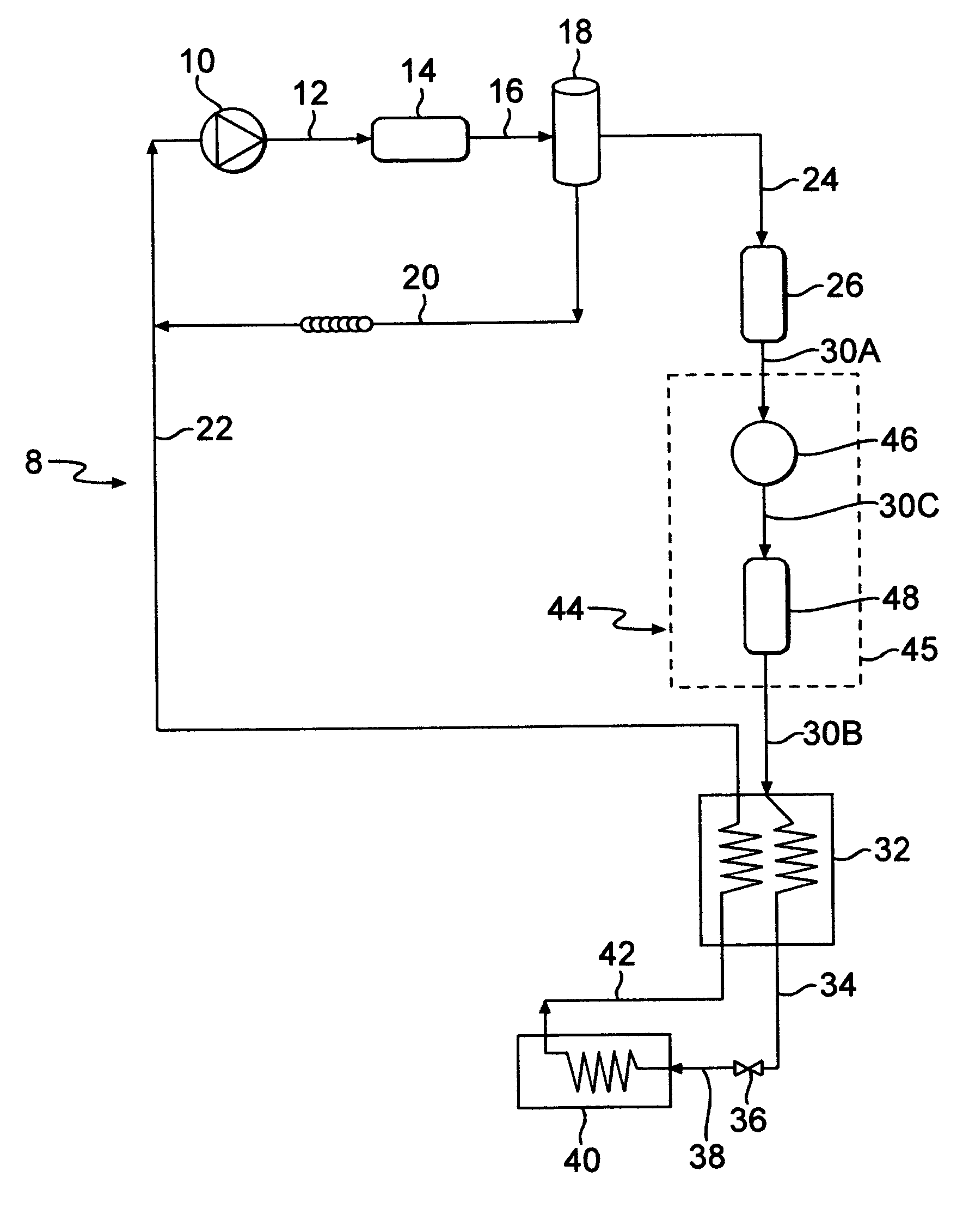
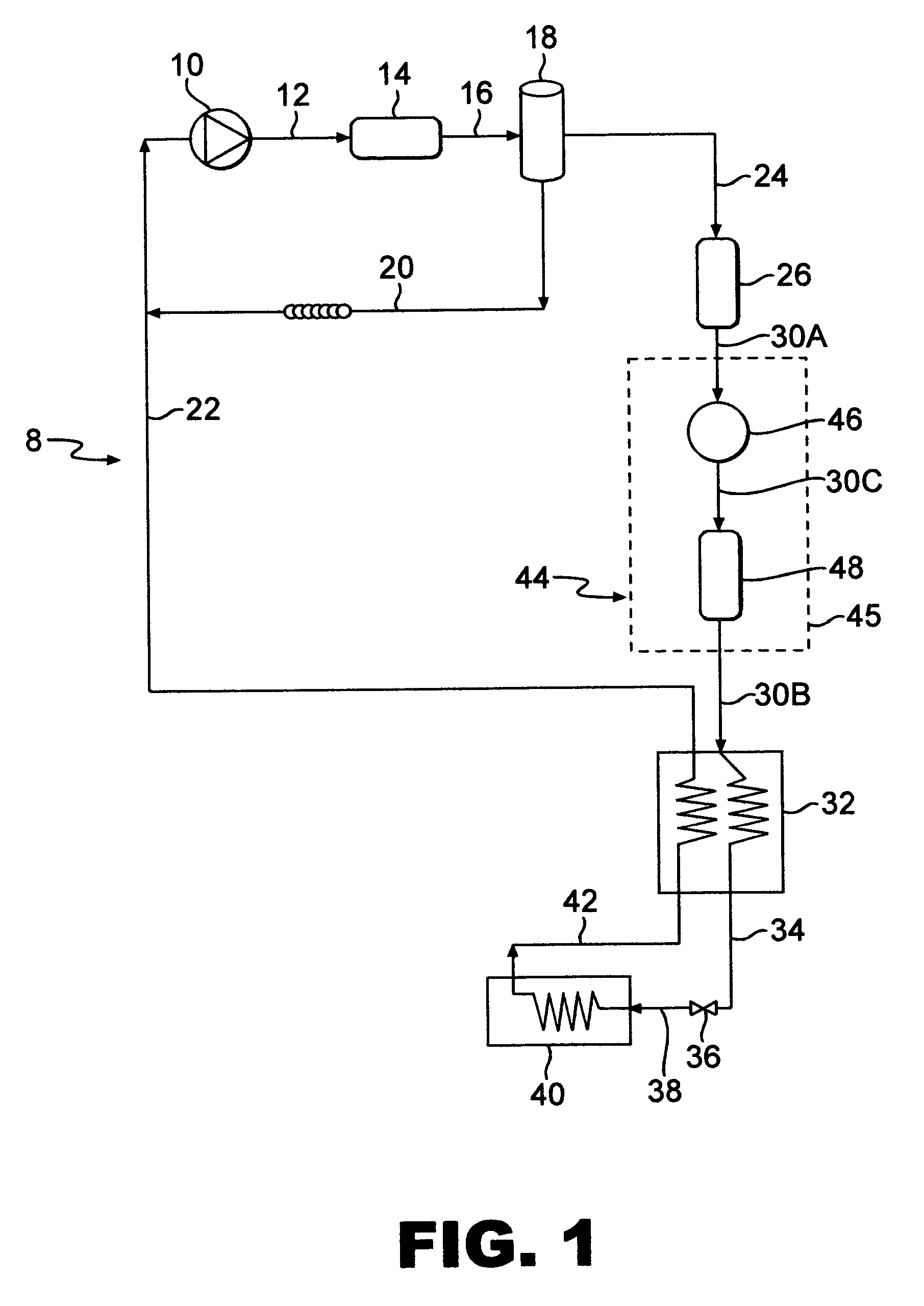
A closed cycle refrigeration system in conjunction with specific mixed or multiple component refrigerant fluids to produce temperatures in the range of 230° K to 70° K. The mixed component refrigerant can be blended from flammable or a non-flammable fluid components based upon the arrangement of the refrigeration equipment and the overall performance requirements for the system. A compressor, an after cooler, an oil separator, filter/dryer, heat exchanger, a throttle device with fixed orifice and an evaporator are arranged in a manner to improve system performance with refrigeration of the present invention or prior art refrigerants. Replaceable additional modules for oil filtration and moisture filtration can be part of the system.

Description

BACKGROUND OF THE INVENTION [0001] Generally, refrigeration cycles, including closed cycle refrigeration systems are well known in the art. In a typical closed cycle refrigeration system intended for household or commercial applications, the system consists of a compressor that compresses the refrigerant, which is then cooled in a condenser, then expanded through an expansion device to produce cold refrigerant which is passed through an evaporator to provide cooling effect to the device or medium to be cooled and then the warmed refrigerant is returned to the compressor. [0002] However, when the temperatures to be achieved are in the semi-cryogenic (230° K to 120° K) or cryogenic range (below 120° K), then efficient and reliable systems are hard to find. This problem is especially critical when temperatures below 120° K, e.g. close to liquid nitrogen condensation / boiling temperature (77° K), are to be achieved. To produce refrigeration at these temperatures a refrigeration system mu...

Claims


Application Information

Patent Timeline
Patent Type & Authority Applications(United States)
IPC IPC(8): C09K5/04F25B9/00F25B40/00F25B43/02
CPCC09K5/042C09K5/045C09K2205/12C09K2205/13F25B2500/01F25B40/00F25B43/02F25B2400/12F25B9/006
Inventor KHATRI, AJAY
Owner ADVANCED RES SYST
Why Eureka
Try Eureka