Lubricating structure for hydraulic driving apparatus
- Summary
- Abstract
- Description
- Claims
- Application Information
AI Technical Summary
Benefits of technology
Problems solved by technology
Method used
Image

Examples
first embodiment
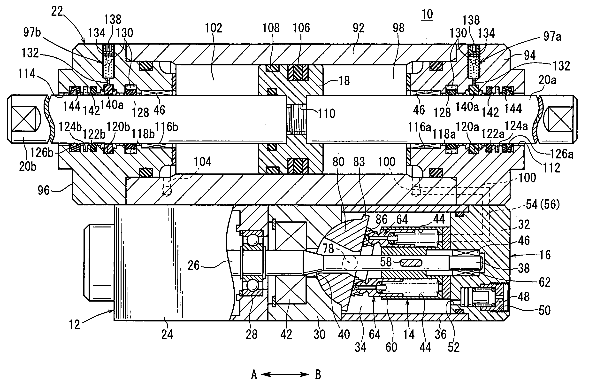
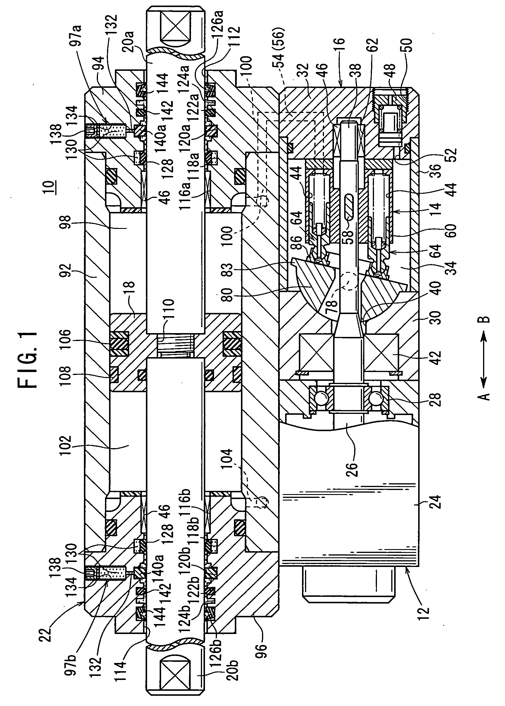
[0018] With reference to FIG. 1, reference numeral 10 indicates an actuator to which a lubricating structure for a hydraulic driving apparatus according to the present invention is applied.
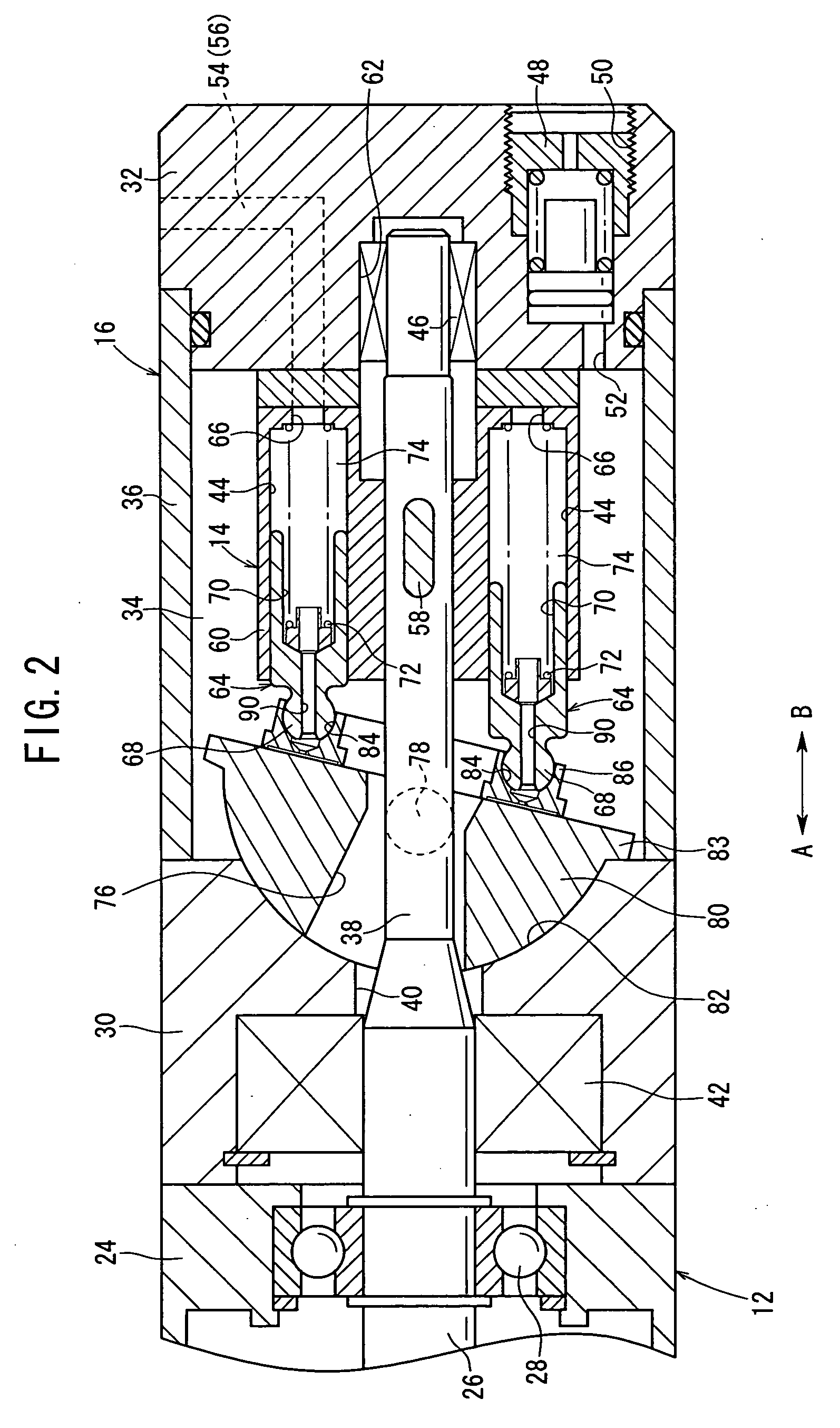
[0019] The actuator (hydraulic driving apparatus) 10 comprises a pump-driving unit 12, which is driven and rotated in accordance with a current, and a pump mechanism 16 including a sucking / discharging section 14, which is integrally connected to the side of the pump-driving unit 12 and which is energized / deenergized by the pump-driving unit 12. The actuator 10 further comprises a cylinder mechanism 22, which is integrally provided on the pump-driving unit 12 and the pump mechanism 16, and which includes a piston 18 that makes displacement in the axial direction in accordance with the supply of operation oil, and first and second piston rods (drive shafts) 20a, 20b connected coaxially with respect to the piston 18.
[0020] The pump-driving unit 12 is composed of, for example, any one of an induction...
second embodiment
[0080] The rotary actuator 200, to which the lubricating structure for a hydraulic driving apparatus is applied, comprises a pump-driving section 12, which is driven and rotated in accordance with a supplied current, a pump mechanism 16, which is integrally connected to the side of the pump-driving section 12 and which includes a sucking / discharging section that is energized / deenergized by the pump-driving section 12, and a rotary driving mechanism 204, which is integrally disposed on sides of the pump-driving section 12 and the pump mechanism 16, and which is driven rotatably about the center of a rotary shaft (drive shaft) 202 in accordance with the supply of operation oil.
[0081] The rotary driving mechanism 204 includes a body 206 which is connected to sides of the pump-driving section 12 and the pump mechanism 16, a rotary shaft 202 which is axially supported rotatably in an insertion hole 208 formed in the body 206, a rotary disk member 212 which is connected to a substantiall...
third embodiment
[0086] The hydraulic continuously variable transmission 250, employing the lubricating structure for the hydraulic driving apparatus comprises a pump-driving section 12 which is driven and rotated in accordance with a supplied current, a pump mechanism 16 which is integrally connected to a side of the pump-driving section 12, and which has a sucking / discharging section that is energized / deenergized by the pump-driving section 12, and a rotary driving mechanism 254 which is integrally provided on sides of the pump-driving section 12 and the pump mechanism 16, and which drives and rotates a rotary shaft 252 in accordance with operation oil supplied thereto.
[0087] The hydraulic continuously variable transmission 250 comprises a so-called HST (Hydro Static Transmission). The pump mechanism 16 and the pump-driving section 12 are connected via piping, wherein the pump mechanism 16 is driven by the engine of a vehicle or the like to feed high pressure oil to the rotary driving mechanism 2...
PUM
 Abstract
Description
Claims
Application Information
 - Generate Ideas
- Intellectual Property
- Life Sciences
- Materials
- Tech Scout
- Unparalleled Data Quality
- Higher Quality Content
- 60% Fewer Hallucinations
Browse by: Latest US Patents, China's latest patents, Technical Efficacy Thesaurus, Application Domain, Technology Topic, Popular Technical Reports.
© 2025 PatSnap. All rights reserved.Legal|Privacy policy|Modern Slavery Act Transparency Statement|Sitemap|About US| Contact US: help@patsnap.com