Friction damper

a technology of friction damper and slit, which is applied in the direction of shock absorbers, mechanical devices, transportation and packaging, etc., can solve the problems of deterioration in characteristics, potential environmental contamination, and deterioration in characteristics, so as to reduce the width of the gap, and reduce the diameter

Inactive Publication Date: 2005-04-28
OILES CORP
View PDF11 Cites 17 Cited by
  • Summary
  • Abstract
  • Description
  • Claims
  • Application Information

AI Technical Summary

Benefits of technology

[0007] In accordance with the friction damper according to the first aspect, the base material of the friction member is a mesh-like material, the sliding layer of the friction member is formed on one surface of the base material in such a manner as to fill the meshes of the base material, and such a sliding layer is disposed on the radially inner peripheral surface side of the hollow cylindrical portion so as to be brought into contact with the rod slidably in its axial direction. Therefore, it is possible to avoid wear with respect to the rod as practically as possible, and obtain stable friction. Furthermore, it is possible to avoid the exfoliation of the sliding layer. Hence, it is possible to obtain stable damping characteristics over a long period of time.
[0030] In accordance with the invention, it is possible to provide a friction damper which has a simple structure, is capable of reducing wear and the exfoliation of the sliding layer as practically as possible, and makes it possible to obtain stable damping characteristics over a long period of time.

Problems solved by technology

In the damper using lead, a steel rods, or the like, there is a risk of environmental contamination due to lead, and it is required to firmly hold both ends of lead, the steel rod, or the like, respectively, to a pair of members which are displaced relative to each other.
Meanwhile, In the damper using a sliding member, there is a possibility of deterioration in characteristics due to the wear of the sliding member.
Further, a sliding layer of the sliding member can peel off, which can also possibly cause deterioration in characteristics.

Method used


Image

  • Friction damper
  • Friction damper
  • Friction damper

Examples


Embodiment Construction

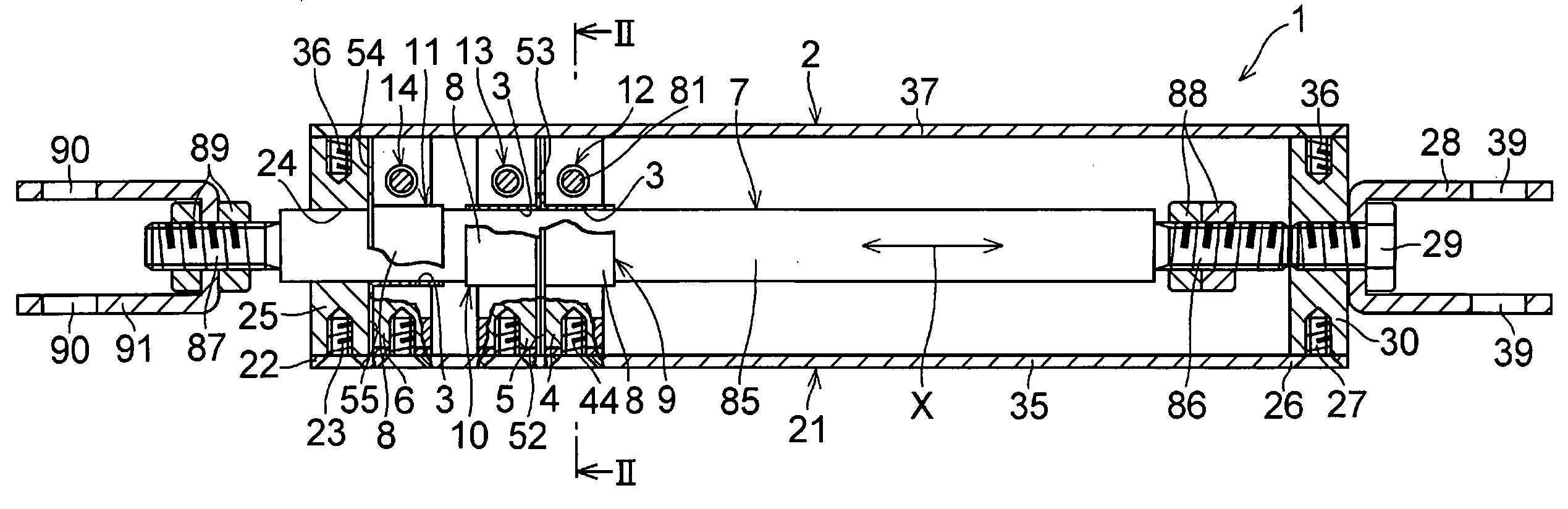
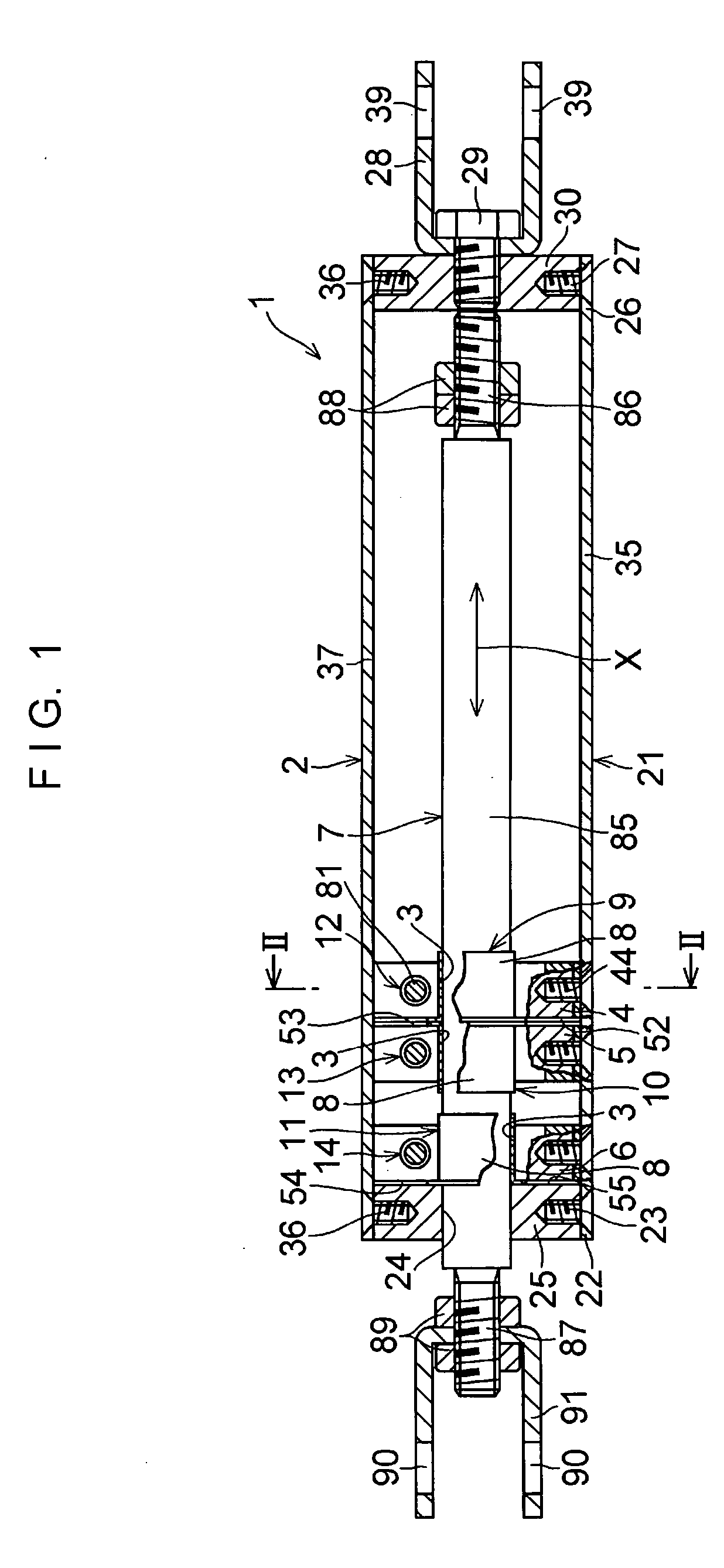
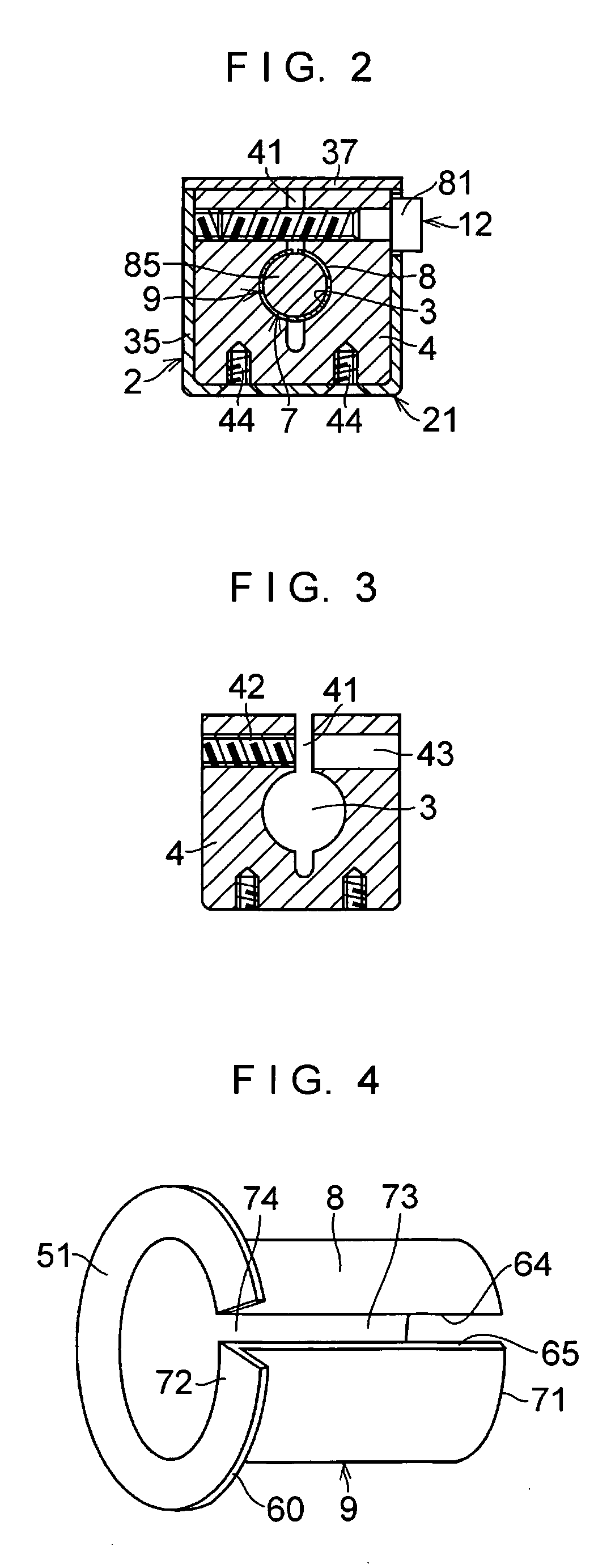
[0046] In FIGS. 1 to 5, a friction damper 1 in accordance with this embodiment is comprised of a base body 2; a plurality of, or in this embodiment three, supports 4, 5, and 6 which are respectively secured to an elongated member 35 of the base body 2, have a through hole 3, and are arranged in an axial direction X; a rod 7 which extends in such a manner as to pass through the respective through holes 3 of the supports 4, 5, and 6, and is movable in the axial direction X with respect to the supports 4, 5, and 6; friction members 9, 10, and 11 each of which has a hollow cylindrical portion 8 interposed between each of the supports 4, 5, and 6 and a cylindrical main body portion 85 of the rod 7 in a corresponding through hole 3 of the support 4, 5, or 6, the frictions members 9, 10, and 11 being fixed immovably with respect to the relative movement of the rod 7 in the axial direction X with respect to the base body 2 and being provided with respect to the respective supports 4, 5, and...


PUM


Abstract

A friction damper includes a base body; a support secured to an elongated member of the base body and having a through hole; a rod which extends in such a manner as to pass through the through hole of the support and is movable in an axial direction with respect to the support; a friction member which has a hollow cylindrical portion interposed between the support and a main body portion of the rod in the through hole of the support, and which is fixed immovably with respect to the relative movement of the rod in the axial direction with respect to the base body; and a tightening structure provided for the support so as to tighten the hollow cylindrical portion of the friction member onto the main body portion of the rod.

Description

TECHNICAL FIELD [0001] The present invention relates to a friction damper which is installed between a pair of members that are displaced relative to each other and which dampens displacement as speedily as possible by absorbing the displacement energy between the members through friction. More particularly, the present invention concerns a friction damper which dampens displacement as speedily as possible by absorbing the displacement energy occurring in structures such as office buildings, multiple dwelling houses, detached houses, bridges, and the like due to earthquakes or the like. BACKGROUND ART [0002] As dampers for speedily damping vibrations such as lateral shaking occurring in a structure due to an earthquake or the like, those using the viscous deformation of a viscous material, those using the plastic deformation of lead, steel rods, or the like, and those using the friction of a sliding member, among others, are known. [0003] In the damper using a viscous material, much...

Claims


Application Information

Patent Timeline
Patent Type & Authority Applications(United States)
IPC IPC(8): E04H9/02F16F7/08F16F7/09F16F15/02
CPCE04H9/02E04H9/028F16F7/08F16F7/09F16F15/02F16F7/082E04H9/0237
Inventor OKIMURA, AKIHIKONAGASHIMA, KAZUHIROTANAKA, GOARAI, YOUKO
Owner OILES CORP
Why Eureka
Try Eureka