Injection device for internal combustion engines comprising a control valve and a valve for controlling the supply of fuel to an injection device

a technology for injection devices and internal combustion engines, which is applied in the direction of valve housings, fuel injecting pumps, machines/engines, etc., can solve the problems of more time lost in the system required to fill this volume, and achieve the effect of reducing the flow rate and simple structur

Inactive Publication Date: 2005-04-28
SIEMENS AG
View PDF5 Cites 0 Cited by
  • Summary
  • Abstract
  • Description
  • Claims
  • Application Information

AI Technical Summary

Benefits of technology

[0006] The object of the present invention is to provide a control valve, whi

Problems solved by technology

The larger the volume selected, the more time is

Method used


Image

  • Injection device for internal combustion engines comprising a control valve and a valve for controlling the supply of fuel to an injection device
  • Injection device for internal combustion engines comprising a control valve and a valve for controlling the supply of fuel to an injection device
  • Injection device for internal combustion engines comprising a control valve and a valve for controlling the supply of fuel to an injection device

Examples


Embodiment Construction

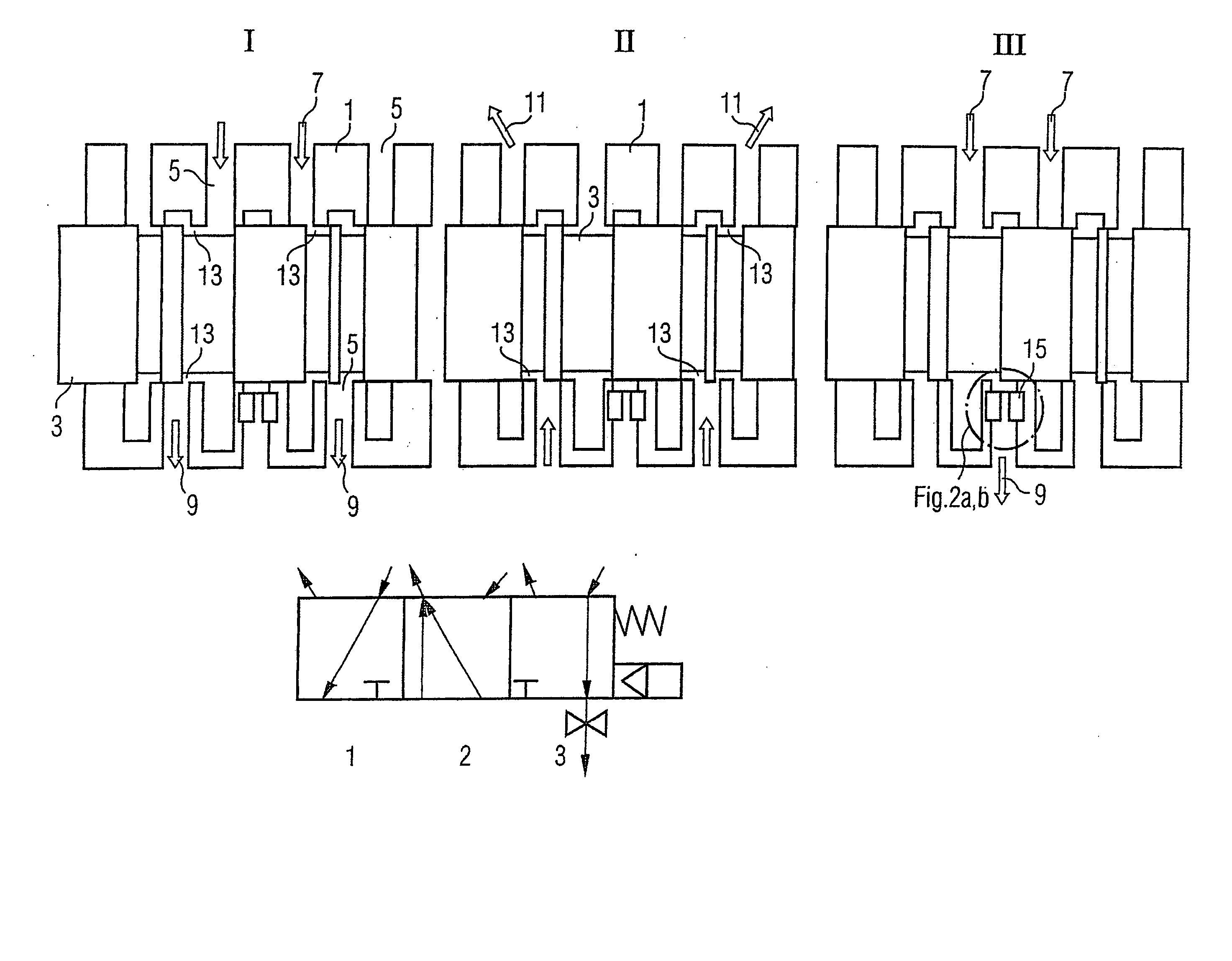
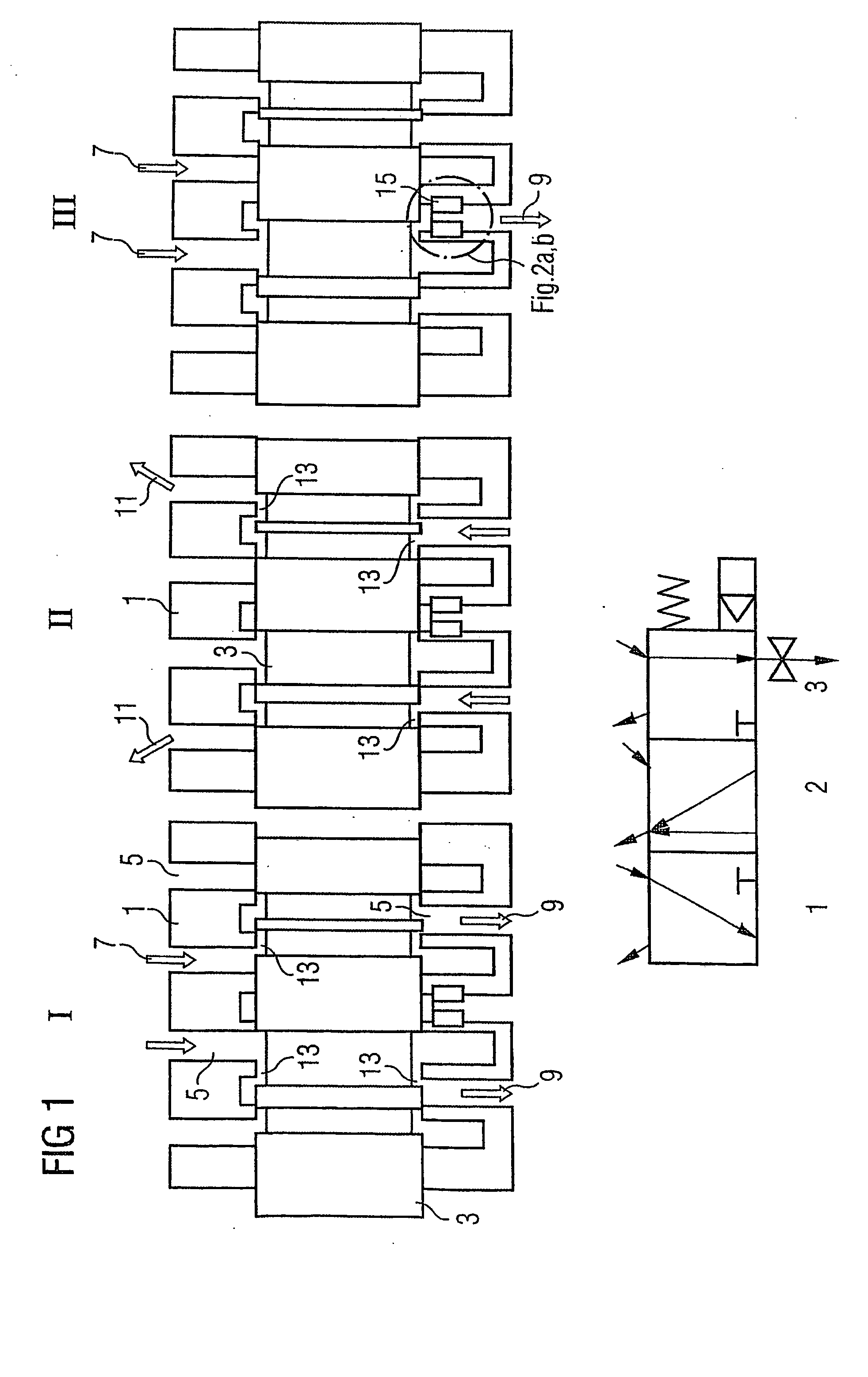
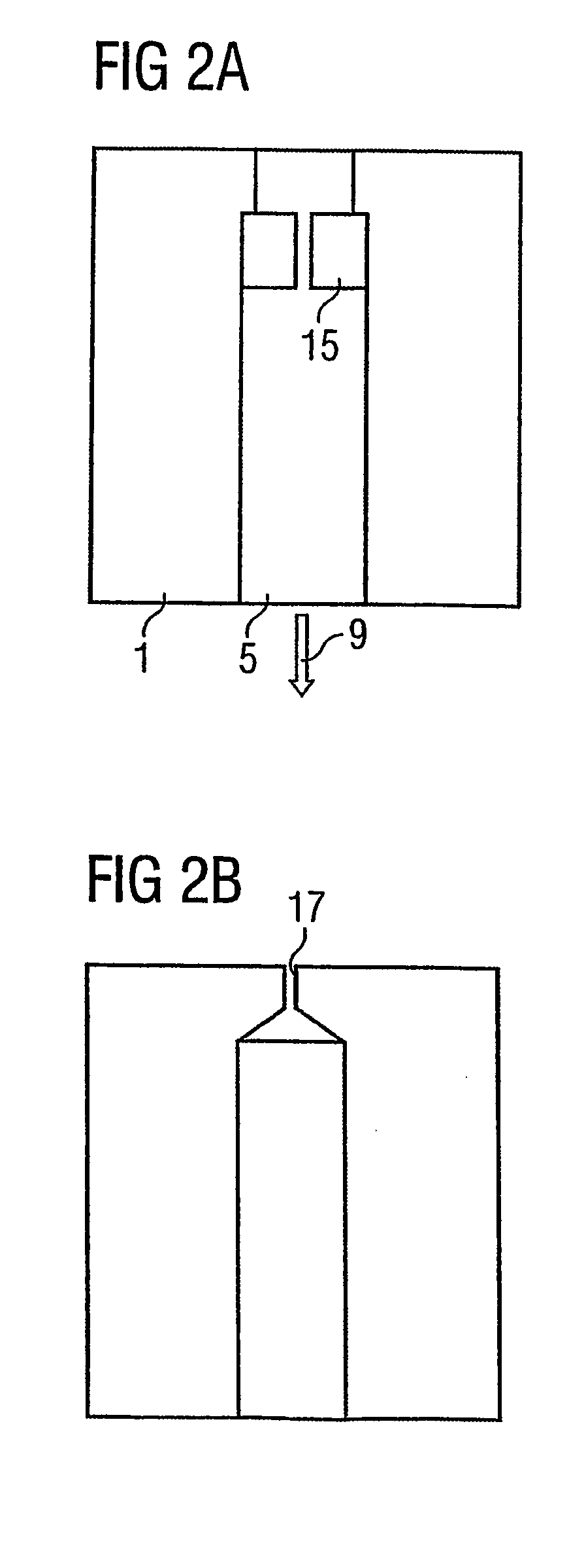
[0014] A three-way control valve for controlling a piston in the pressure intensifier of an injection valve for internal combustion engines (not shown) comprises a control valve piston 3 arranged in a control valve housing 1. The axial position in the valve housing 1 is controlled by a known control device (not shown). Different radial fluid lines 5 are embodied in the control valve housing 1 by means of bores. A rail 7, a pressure intensifier 9 and a distributing canal 11 can be controlled by means of these, in connection with one another. In accordance with FIG. 1, the three-way control valve comprises three operating positions or positioning options for the control valve piston 3 (I, II, III). In position I the valve connects the fluid supply from the rail 7 to the pressure intensifier 9 by means of two flow paths with a first flow rate D1. This is also determined by means of the free opening cross-section between the control piston 3 and the corresponding control edges and the r...


PUM


Abstract

A known control valve, especially for controlling a piston of a pressure intensifier of an injection device for internal combustion engines is already known per se. Said control valve comprises a control valve housing, fluid lines and a control valve piston which can be displaced in a controlled manner in the housing in at least two operational positions. Said piston controls at least the fluidic connection between a first chamber and a second chamber having a first flow rate or a reduced second flow rate. In order to produce said control valve which enables the precise control of the reduced second flow rate and which is simple to construct, a throttle is provided. Said throttle adjusts the reduced second flow rate and is arranged outside the control valve piston and in front of the second chamber.

Description

CROSS-REFERENCE TO RELATED APPLICATION OR PRIORITY [0001] This application is a continuation of co-pending International Application No. PCT / DE03 / 01071 filed Apr. 1, 2003 which designates the United States, and claims priority to German application number DE10215981.5 filed Apr. 11, 2002.FIELD OF THE INVENTION [0002] The present invention relates to an injection device for internal combustion engines and a valve for controlling the supply of fuel to an injection device. BACKGROUND OF THE INVENTION [0003] A control valve is known from U.S. Pat. No. 5,460,329, wherein a working medium controls a pressure intensifier by means of moving the control valve piston. On the other hand, the movement of the pressure intensifier piston correspondingly controls the movement of a valve needle in an injection valve for a fuel injection process. The control valve piston thus comprises control edges by means of which the flow of the working medium is controlled using the control valve. [0004] Furthe...

Claims


Application Information

Patent Timeline
IPC IPC(8): F02M45/06F02M45/02F02M47/00F02M57/02F02M59/10F02M59/34F02M59/46F16K11/07F16K27/02F16K27/04
CPCF02M45/02F02M57/025F02M59/105F02M59/34F02M59/466F16K27/029F02M63/0047F16K11/07F16K27/0263F16K27/041F02M63/004
Inventor ASTACHOW, ANDREJWARGA, JOHANN
Owner SIEMENS AG
Why Eureka
Try Eureka