Method and system for a pellicle frame with heightened bonding surfaces (as amended)

a technology of bonding surface and pellicle, which is applied in the field of photolithography systems, can solve the problems that the ambient atmosphere of the clean room cannot be purged of oxygen, adversely affecting the photolithography process, etc., and achieve the effect of reducing or eliminating reticle or pellicle distortion

Inactive Publication Date: 2005-04-28
ASML HLDG NV
View PDF13 Cites 7 Cited by
  • Summary
  • Abstract
  • Description
  • Claims
  • Application Information

AI Technical Summary

Benefits of technology

[0011] The passive or static porous frame acts to normalize the pressure within the reticle to pellicle gap with the external ambient air atmosphere. This normalization action effectively reduces or eliminates distortion of either the reticle and / or pellicle due to atmospheric pressure.
[0016] The purge gas flow in the gap of a dynamic porous frame may be balanced with an external atmospheric pressure to reduce or eliminate reticle or pellicle distortions.

Problems solved by technology

In some situations, the ambient atmosphere of the clean room cannot be purged of oxygen because this may cause other problems with the photolithography process.
Furthermore, the pellicle and / or reticle can become distorted when attached to the frame, adversely affecting the photolithography process.

Method used


Image

  • Method and system for a pellicle frame with heightened bonding surfaces (as amended)
  • Method and system for a pellicle frame with heightened bonding surfaces (as amended)
  • Method and system for a pellicle frame with heightened bonding surfaces (as amended)

Examples


Embodiment Construction

[0043] To more clearly delineate the present invention, an effort is made throughout the specification to adhere to the following term definitions as consistently as possible.

[0044]“Ambient air” means an oxygen-containing atmosphere, such as normal atmospheric air. For instance, “ambient air” may mean air in an oxygen-containing clean room atmosphere or environment.

[0045]“Purge gas” means a gas that does not contain oxygen, or some other undesired gas, and is used to fill a purged air gap or space.

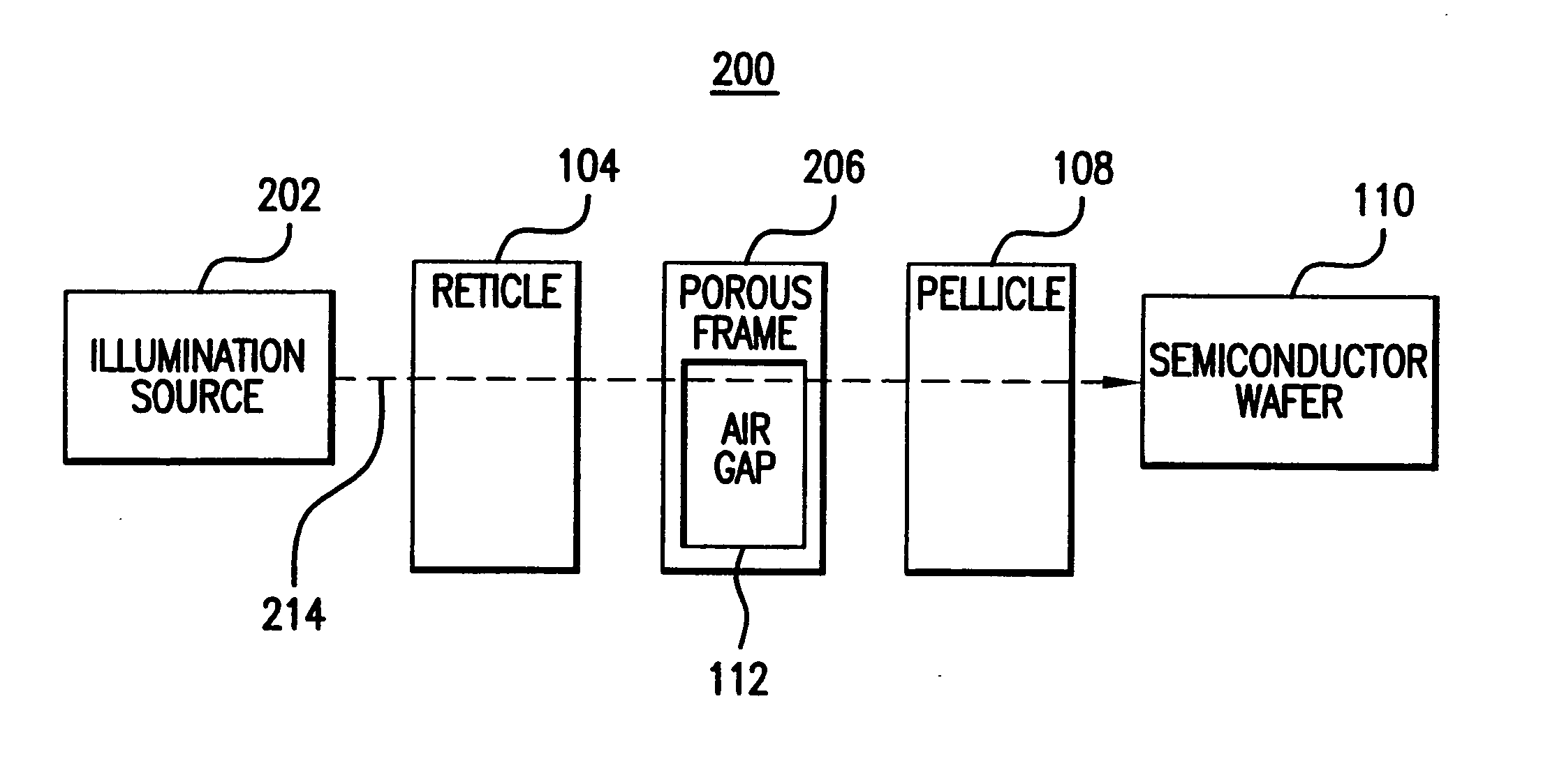
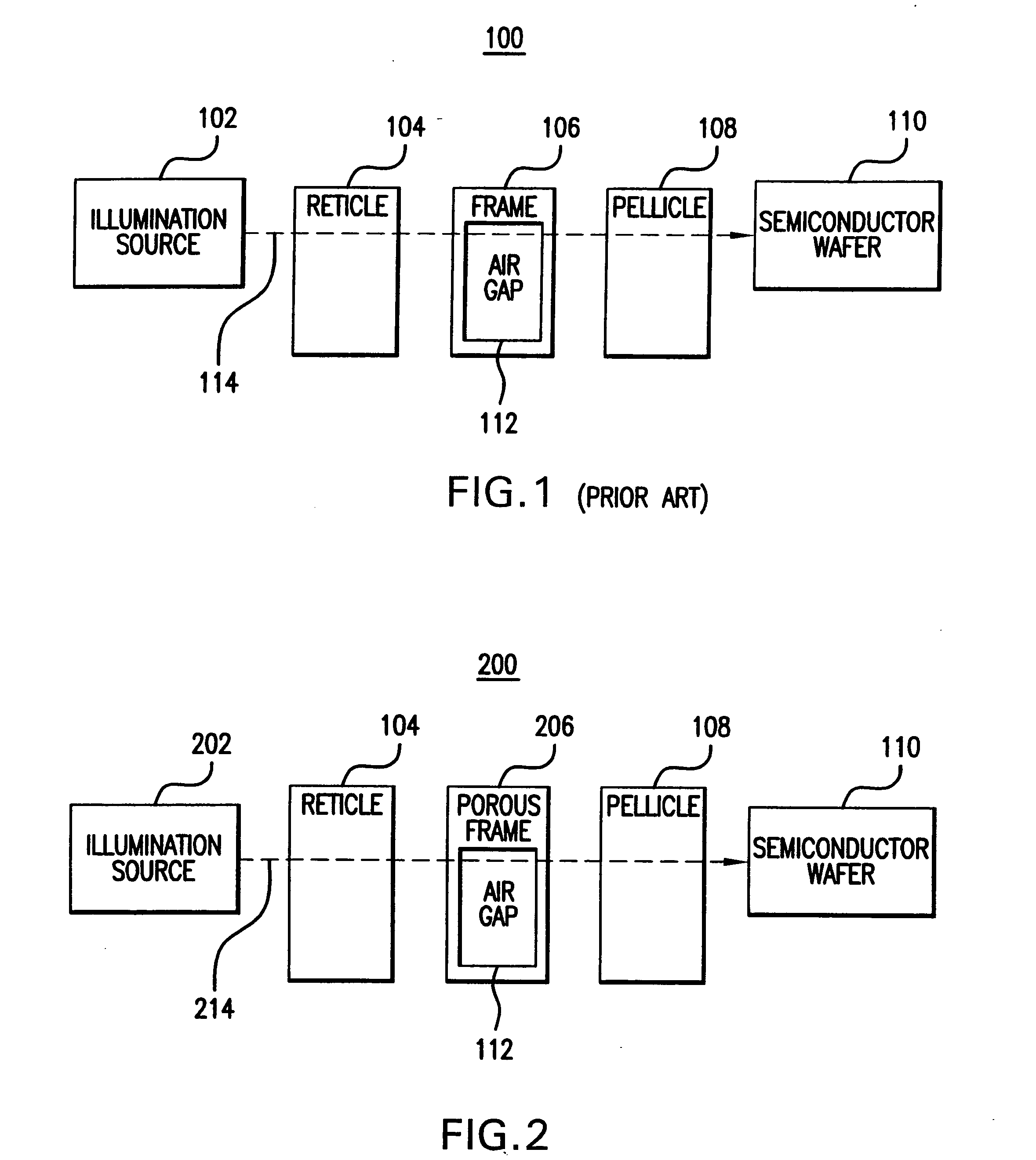
[0046]FIG. 1 illustrates a relevant portion of a conventional photolithography system 100. Conventional photolithography system 100 is located in an ambient air or gas environment. Some portions of a conventional photolithography system may not be shown in FIG. 1 for purposes of brevity, such as source optics, projection optics, etc.

[0047] Conventional photolithography system 100 comprises an illumination source 102, a reticle 104, a frame 106, a pellicle 108, and a semiconductor wafer...


PUM

PropertyMeasurementUnit
light wavelengthsaaaaaaaaaa
optical gapaaaaaaaaaa
optical structureaaaaaaaaaa

Abstract

A method and apparatus for maintaining an optical gap between optical structures in a photolithography system is described. A frame defines first and second opposing surfaces. The first opposing surface defines a first opening and the second opposing surface defines a second opening. A plurality of spacing members are spaced apart on the first opposing surface around the first opening. The spacing members have substantially co-planar surfaces configured to mate with a surface of a first optical structure. A bonding agent seals a space around the first opening between the first opposing surface and the first optical structure. The frame thereby encloses the optical gap between the first optical structure and a second optical structure.

Description

BACKGROUND OF THE INVENTION [0001] 1. Field of the Invention [0002] The present invention is generally related to photolithography systems, and more particularly, to pellicle and reticle frames in a photolithography system. [0003] 2. Background Art [0004] In the fabrication of integrated circuits, photolithographic and projection printing techniques are used. In photolithography, an image contained on a reticle is projected onto a wafer having a photosensitive resist thereon. The reticle or mask is used to transfer a desired image onto the silicon wafer. The semiconductor wafer surface is coated with photosensitive resist so that an image is etched thereon. A pellicle may be used in combination with the reticle to protect the reticle surface from damage. The pellicle is traditionally mounted on a solid frame to the reticle. [0005] Some wavelengths of light used in photolithography are sensitive to absorption by atmospheric oxygen. Hence, when such oxygen-sensitive light wavelengths ...

Claims


Application Information

Patent Timeline
Patent Type & Authority Applications(United States)
IPC IPC(8): G03F7/20
CPCG03F7/70983G03F1/64
Inventor LAGANZA, JOSEPHIVALDI, JORGE
Owner ASML HLDG NV
Why Eureka
Try Eureka