Feedback control of an interferometer

a technology of interferometer and feedback control, which is applied in the direction of electromagnetic transmission, optical radiation measurement, instruments, etc., can solve the problems of inability to realize manual adjustment, inability to control dli in the same way, and no direct effect on the amplitude of the signal

Inactive Publication Date: 2005-04-28
RPX CORP +1
View PDF4 Cites 60 Cited by
  • Summary
  • Abstract
  • Description
  • Claims
  • Application Information

AI Technical Summary

Benefits of technology

[0017] Particularly advantageously the method can be utilized for the demodulation of a DPSK modulated optical signal and / or for generating a duobinary coding of an optical signal. With particular advantage the generating of the third electrical signal further comprises generating the difference of the first and the second electrical signal.
[0018] Especially by this, the invention has the advantage over known methods that the carrier of the transmitted spectrum does not have to be detected, which would lead to a signal distortion. Instead, the RF signal power (Radio Frequency) is detected by generating the difference of the first and the second electrical signal and from that the feedback signal is generated. Hence the DLI is controlled without the carrier signal.

Problems solved by technology

This results from the fact that the functionality of an interferometer fundamentally relies on the exactly constructive and destructive interference between two optical fields.
A DLI however cannot be controlled in the same way, because the signal, in contrast to a MZM, interferes with a delayed version of itself, resulting in no direct effect on the amplitude of the signal.
In a commercial system however a manual adjustment cannot be realized.
This however disadvantageously requires a deliberate detuning of the phase modulator to a certain extent and results in a signal distortion.

Method used


Image

  • Feedback control of an interferometer
  • Feedback control of an interferometer
  • Feedback control of an interferometer

Examples


Embodiment Construction

[0045] In the embodiments described hereinafter the DLI 20 is utilized as a demodulator for a DPSK modulated optical signal. However, the invention is not limited to this purpose. For instance the DLI 20 could also be used for the modulation of a duobinary coding or for other modulation and / or demodulation purposes.

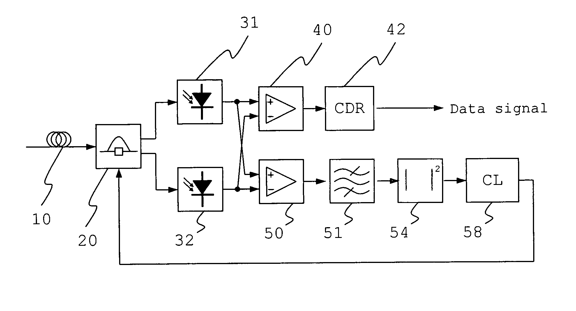
[0046]FIG. 1 shows a block diagram of a first embodiment of an inventive feedback control device. Via an optical fiber 10 a DPSK modulated optical signal is received and fed into the input of the DLI 20 in which the signal is demodulated. The optical output signals of the DLI, which are phase-shifted by π / 2 radian, are fed into a first 31 and a second 32 photo diode respectively and are converted into electrical signals by means of said photo diodes.

[0047] The device is provided with two circuit branches, a data branch and a feedback branch.

[0048] In the data branch the electrical signals of the photo diodes 31 and 32 are fed into a first differential amplifier 40 in s...


PUM


Abstract

The invention proposes a method for feedback control, in which a portion of a data signal is split and rectified and the signal intensity is detected with slow speed electronics for improving the control of a delay line interferometer (DLI) used in optical data transmission. A control signal is generated and fed back to the DLI based on the detected signal intensity. The invention further proposes a device provided with a DLI, a first and second optoelectronic component, and a differential amplifier.

Description

CROSS-REFERENCE TO RELATED APPLICATIONS [0001] This application claims priority of European Application No. 103 49 736.6 filed on Oct. 23, 2003. BACKGROUND OF THE INVENTION [0002] 1. Technical Field [0003] The invention relates to data transmission via optical signals in general and especially to a method and a device for automatic control of a delay line. [0004] 2. Description of the Related Art [0005] For data transmissions in telecommunication and for data transfer optical signals are increasingly employed. In the past years the speed of data transmission via fiber optical connections increased quite considerably. [0006] To achieve high bandwidths in optical data transmission advanced modulation formats are required. While amplitude modulation is still predominant, advanced modulation formats often make use of an additional phase modulation. Among the advanced modulation formats which will be implemented first due to their simplicity are duobinary coding and differential phase sh...

Claims


Application Information

Patent Timeline
Patent Type & Authority Applications(United States)
IPC IPC(8): G01B9/02G01J9/00H04B10/67H04B10/69
CPCH04B10/67H04B10/69H04B10/676
Inventor SCHLENK, RALPHSTAHL, DAVID
Owner RPX CORP
Why Eureka
Try Eureka