Use of IR camera

a technology of ir camera and ir beam, which is applied in the field of ir beam camera, can solve the problems of high-risk areas, time-consuming measurements, and increased condensation risk of damp damage, and achieve the effect of reliable results

Active Publication Date: 2005-04-28
FLIR SYST AB
View PDF3 Cites 14 Cited by
  • Summary
  • Abstract
  • Description
  • Claims
  • Application Information

AI Technical Summary

Benefits of technology

[0005] It is therefore an object of the present invention to enable inspection of large a

Problems solved by technology

Such condensation increases the risk of damage due to damp.
There is thus a risk that high-risk areas are missed, and/or the measurements may be time-consuming.
Further, such inspections often involve imaging in pl

Method used


Image

  • Use of IR camera
  • Use of IR camera
  • Use of IR camera

Examples


Embodiment Construction

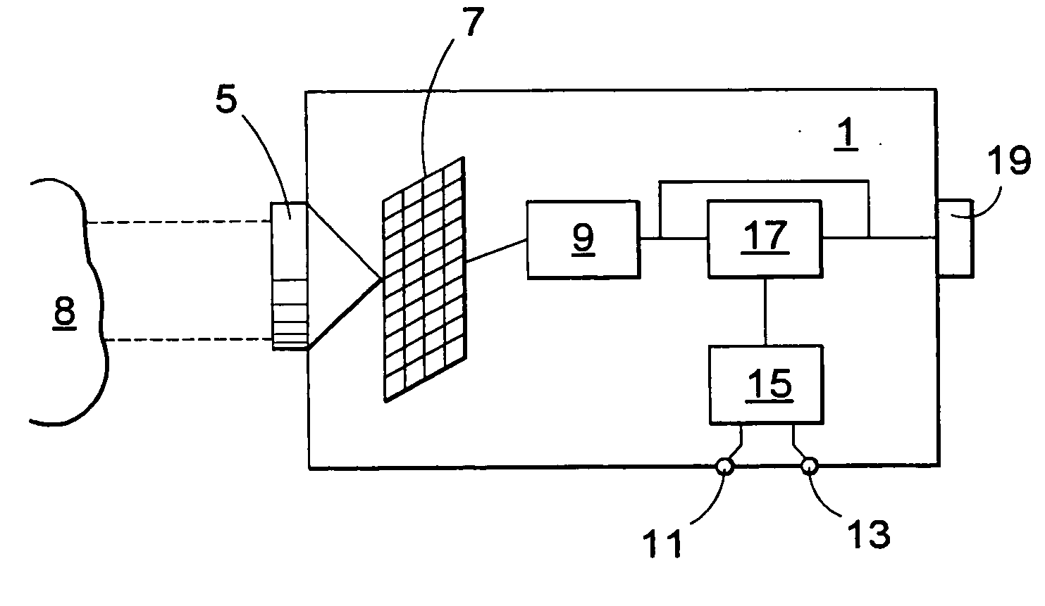
[0048]FIG. 1 shows an IR camera according to the invention. For registering IR images the camera unit 1 comprises the same functions as prior art cameras. The gathering of data and the data processing performed prior to displaying the image are carried out in the conventional way. This technology is known to the skilled person, but will be briefly discussed in the following. The incoming radiation to the camera is focused by at least one lens 5 onto a detector array 7. The detector array is typically a matrix of detector elements, each detecting radiation from a corresponding area on an object 8 being imaged. From the detector array the signal is fed to a signal conditioning unit 9 which performs conventional signal conditioning such as corrections for the inherent offset and gain drift.

[0049] It should be noted that the IR camera does not necessarily comprise a focal plane array. The inventive concept can also be implemented in an IR camera using an IR scanner.

[0050] According to...


PUM


Abstract

The inventive IR camera is used to identify areas of a surface in which there is an increased risk of condensation, by imaging the surface determining, from humidity and temperature values, a condensation temperature at which there is a risk of condensation on the surface, comparing the temperature in at least one image point registered by the camera to the condensation temperature colouring any image points having a temperature lower than the condensation temperature in a particular colour, or grey tone, selected to indicate an increased risk of condensation.

Description

TECHNICAL FIELD [0001] The present invention relates to a method of determining at least one area of a surface in which there is an increased risk of condensation and to the use of an IR camera as defined in the preamble of claim 7. [0002] It also relates to a method for identifying areas on a surface that have an increased risk of condensation and an IR camera as defined in the preamble of claim 13. BACKGROUND AND PRIOR ART [0003] In many applications, in particular when inspecting buildings, there is a need to be able to determine the specific points or areas where there is an increased risk of condensation. Such condensation increases the risk of damage due to damp. Prior art methods for such inspections include conductivity measurements. Conductivity sensors usually measure the conductivity in one particular point and are therefore limited to rather small areas. To make a time-efficient inspection, therefore, areas that are assumed to have an increased risk are selected by the p...

Claims


Application Information

Patent Timeline
IPC IPC(8): G01N25/66H04N5/33
CPCH04N5/33G01N25/66
Inventor LINDSTROM, KJELLKONIG, CHRISTOPH
Owner FLIR SYST AB
Why Eureka
Try Eureka