Hydraulic tensioner

a hydraulic tensioner and plunger technology, applied in the field of hydraulic tensioners, can solve the problems of preventing the rapid and accurate assembly of the tensioner, damage to the entire timing drive system, and failure of the pawl to engage the ratchet teeth properly, so as to improve the durability of the tensioner, prevent the retraction of the plunger, and suppress the effect of noise and breakag

Active Publication Date: 2005-04-28
TSUBAKIMOTO CHAIN CO
View PDF1 Cites 13 Cited by
  • Summary
  • Abstract
  • Description
  • Claims
  • Application Information

AI Technical Summary

Benefits of technology

[0011] The engagement of the check valve with the recess in the bottom of the hole in the outer body, locks the inner body against rotation due to torsion exerted by the compression spring. The locking of the inner body against rotation ensures uniform engagement between the ratchet teeth of the plunger and pawl, thereby reliably preventing retraction of the plunger, suppressing noise and breakage, and improving the durability of the tensioner.
[0012] The material of the outer body may be an aluminum alloy, a ferrous material or the like. However, because of the manner in which rotation of the inner body is prevented, the

Problems solved by technology

The ability of the metal cylinder to twist prevents rapid and accurate assembly of the tensioner.
Moreover, twisting of the metal cylinder can prevent proper engagement of the ratchet pawl 561 with the ratchet teeth 541 on the plunger, preventing reliable application of tension to the transmission medium, causing vibration and noise due to reverse movement of the plunger, and potentially causing damage to the entire

Method used


Image

  • Hydraulic tensioner
  • Hydraulic tensioner
  • Hydraulic tensioner

Examples


Embodiment Construction

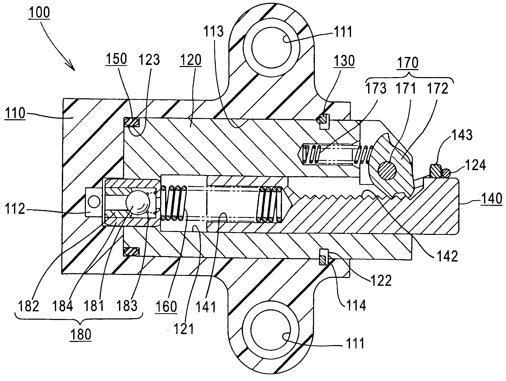
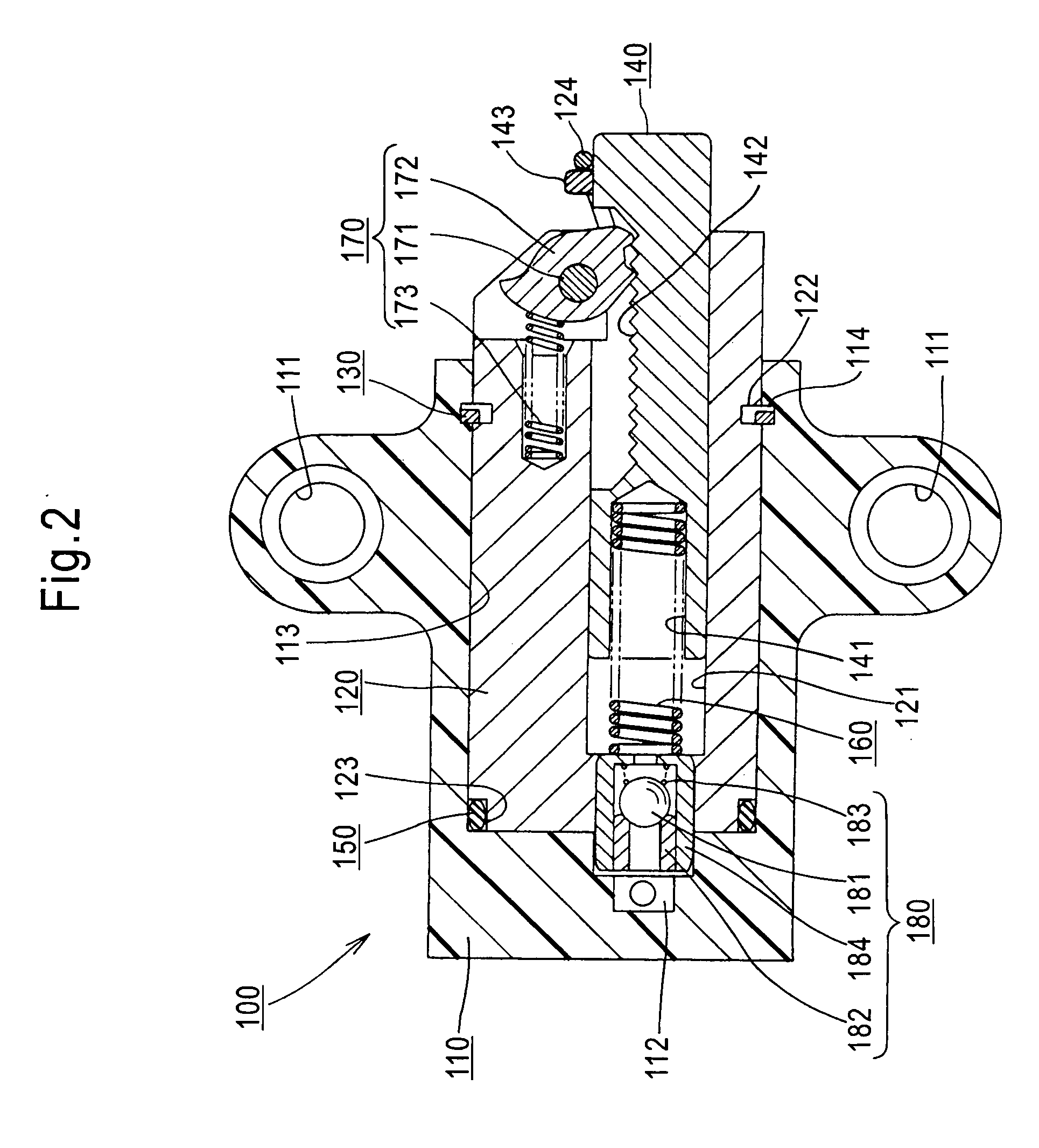
[0021] As shown in FIG. 1, a hydraulic tensioner 100 in accordance with the invention is mounted inside an engine block E for maintaining proper tension in an endless chain transmission comprising a chain C in mesh with a driving sprocket S1, on the crankshaft of an automobile engine, and two driven sprockets S2, each being on a camshaft. The tensioner 100 comprises an outer body 110, which is attached to the engine block E and an inner body 120, which exerts a force on a pivoted chain guide G1, which in turn, applies tension to the timing chain C. A fixed guide G2 is provided on the opposite side of the transmission for stabilizing the traveling path of the chain.

[0022] As shown in FIG. 2, the outer body 110 is preferably molded, by injection-molding, from a synthetic resin, and includes a tensioner mounting ears, each having a mounting hole 111 for mounting the tensioner on an engine block. In this example, the mounting holes 111 are disposed symmetrically for mounting the tensio...


PUM


Abstract

In a hydraulic tensioner, a check valve provided on the rear end of a circular, cylindrical inner tensioner body, fits into a recess formed in the bottom of a hole in an outer body which receives the inner body. The check valve is radially offset from the center line of the inner body, and its engagement with the recess secures the inner body against rotation relative to the outer body.

Description

FIELD OF THE INVENTION [0001] This invention relates to tensioners for maintaining proper tension in endless, flexible power transmission media such as timing chains, a timing belts, or the like, used, for example, in an internal combustion engine in an automobile. More specifically, the invention relates to improvements in hydraulic tensioners of the kind that utilize engine lubricating oil supplied under pressure through an engine block. BACKGROUND OF THE INVENTION [0002]FIG. 5 shows an example of a known hydraulic tensioner used in the timing drive system of an automobile engine or the like. The tensioner comprises a synthetic resin body 510, which can be attached to the side of an engine block, a metal cylinder 520 fitted into a circular hole 511 formed in the body 510, a plunger 540 inserted into the metal cylinder 520 in such a manner that the tip of the plunger 540 protrudes from the body 510, and a compression spring 530, inside the metal cylinder 520, for urging the plunger...

Claims


Application Information

Patent Timeline
IPC IPC(8): F16H7/08
CPCF16H7/0836F16H2007/0806F16H2007/0859F16H2007/0853F16H2007/0812
Inventor YOSHIDA, OSAMU
Owner TSUBAKIMOTO CHAIN CO
Why Eureka
Try Eureka