Distal protection device with electrospun polymer fiber matrix

Inactive Publication Date: 2005-04-28
EV3
View PDF40 Cites 140 Cited by
  • Summary
  • Abstract
  • Description
  • Claims
  • Application Information

AI Technical Summary

Benefits of technology

[0016] The present invention provides an improved device for preventing passage of particulate material entrained in a fluid flowing through a lumen. The device includes a collapsible and expandable filter, wherein the filter has a wire frame and a fiber matrix secured to the wire frame. The present invention provides a filter having a shape as determined by the configuration of the wire frame and a pore size, patency, and crossing profile as determined by the fiber matrix secured to the wire frame.
[0020] The frame will reinforce the filter such that a filter can be made with fine pore size and the combination will have better strength and finer pore size than by use of either a frame or a fiber matrix alone.
[0021] A distal protection device includes a host wire and an expandable, collapsible filter. The filter is preferably secured to the host guidewire at a distal region of the host guidewire. In the expanded configuration, the filter has a periphery expanding outwardly from the host guidewire. In the collapsed configuration the periphery is collapsed toward the host guidewire. The filter in the collapsed configuration has a low-profile diameter, also called a crossing profile, for positioning the distal protection device in a lumen. In the expanded configuration, the filter has a diameter at least as large as that of the lumen diameter. The filter in the expanded configuration prevents the passage of particulate material entrained in a fluid in the lumen while allowing the passage of the fluid.

Problems solved by technology

In the field of medicine, for example, a substantial health risk exists when deposits of fatty—like substances, referred to as atheroma or plaque, accumulate on the wall of a blood vessel.
Stent deployment may also result in emboli dislodgement.
These emboli then become entrained in the blood of the blood vessel and can pose a health risk if the emboli flow to other parts of the vasculature and become lodged therein, creating an occlusion.
In some of these procedures, there is a risk that a deposit may dislodge causing particulate matter to become entrained in the fluid.
Once entrained, the particulate matter may travel downstream and cause a blockage or restrict flow to a smaller vessel elsewhere in the vasculature.
This action can cause a stroke or heart attack in the patient.
Second, it must allow the passage of fluid.
The filaments of such devices are relatively large in relation to the size of particulate sought to be captured, thus making small pore sizes difficult to achieve.
Therefore, these devices constructed in this way are mainly constructed having larger pores so as to filter larger particulate matter and are, therefore, less successful at filtering smaller matter.
Such devices may capture smaller particulate than the intersecting filament device described above, but there is a limit to the smallest pore size that can produced in films using machining or laser drilling techniques.
If the film is made thin to more readily permit small pore sizes the film becomes weak.
In a further limitation of film devices, the filter material must be folded in the collapsed configuration, leading to difficulty maintaining a smaller diameter, as preferred, in the collapsed configuration.
Both intersecting filament and perforated film devices can have a disadvantage of less open area for the passage of fluid.
This results in decreased patency of the filter due to the combination of large non-perforated regions with blood stasis zones distal to these regions, and the comparatively high blood flow rates through the limited number of holes leading to shear activation of thrombus forming blood components.
Further, the limited percent open area of these devices renders them susceptible to clogging of the pores with debris, diminishing patency due to mechanical reasons.
Similar problems exist in many other fields, wherein fluid is transferred through a lumen / vessel.

Method used


Image

  • Distal protection device with electrospun polymer fiber matrix
  • Distal protection device with electrospun polymer fiber matrix
  • Distal protection device with electrospun polymer fiber matrix

Examples


Embodiment Construction

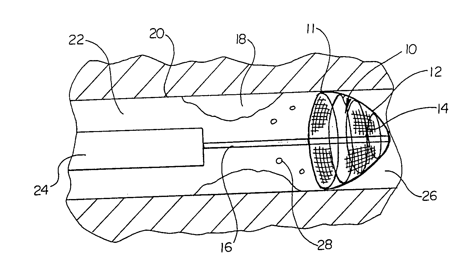
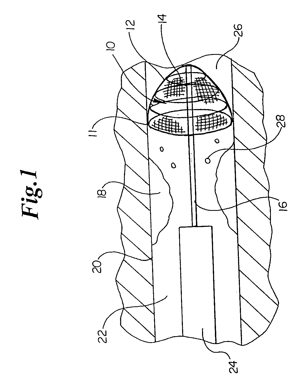
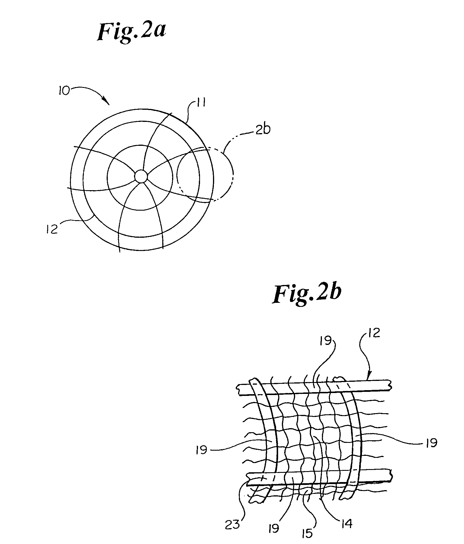
[0033] The present invention embodies an expandable filter 10 for use in a distal protection device 36. The distal protection device 36 comprises the filter 10 attached to a guidewire 16. The protection device 36 has an expanded configuration (as seen in FIG. 4) and a collapsed configuration (as seen in FIG. 3). In the expanded configuration the filter 10 has a periphery 11 extending outwardly from guidewire 16. In the collapsed configuration of FIG. 3, the periphery 11 of the filter 10 collapses towards the guidewire 16. The filter 10 has a wire frame 12 over which is overlain a fiber matrix 14. The filter 10 thereby defines a plurality of pores 15. The pores 15 have a boundary formed by one or more fibers, wires, or a combination thereof.

[0034] In use, the filter 10 is positioned in a lumen 22 by advancing the distal protection device 36 through the lumen 22 in the collapsed configuration shown in FIG. 3. Once positioned, the distal protection device is deployed into the expanded...


PUM


Abstract

The present invention relates to a protection device for use in a lumen of a patient's body. The protection device has a fiber matrix electrospun about an expandable and collapsible wire frame. In the collapsed configuration the protection device may be advanced within a lumen. In the expanded configuration, the protection device is able to engage the walls of the lumen wherein, the fiber matrix forms a plurality of pores for preventing the passage of particulate material and allow fluid to flow through.

Description

[0001] This Application claims the benefit of provisional application Ser. No. 60 / 264,175, filed Jan. 25, 2001, the contents of which are hereby incorporated herein by reference. This application is a continuation of U.S. Ser. No. 10 / 056,588, filed Jan. 23, 2002, the contents of which are hereby incorporated herein by reference.BACKGROUND OF THE INVENTION [0002] The present invention relates to devices used in the treatment of stenotic or obstructed vessels or lumens carrying fluid. More specifically, the present invention relates to an improved protection device for the capturing of particulate matter entrained in a vessel while allowing the passage of fluid through the vessel. [0003] In the field of medicine, for example, a substantial health risk exists when deposits of fatty—like substances, referred to as atheroma or plaque, accumulate on the wall of a blood vessel. A stenosis is formed where such deposits form an obstruction restricting or occluding the flow of blood through t...

Claims


Application Information

Patent Timeline
IPC IPC(8): A61F2/01A61B17/00
CPCA61F2/01A61F2/013A61F2002/018A61F2230/0006A61F2230/0093A61F2230/0067A61F2230/0069A61F2230/0076A61F2230/008A61F2230/0008A61F2/0108A61F2/0105
Inventor PAVLOVIC, JENNIFER L.
Owner EV3
Why Eureka
Try Eureka