Turbine blade and a method of manufacturing and repairing a turbine blade

a technology of turbine blades and manufacturing methods, which is applied in the field of turbine blades, can solve the problems of reducing the thickness of the blade airfoil, difficult and time-consuming to remove the ceramic core, and difficulty in the manufacture of turbine blades

Inactive Publication Date: 2005-05-05
CHROMALLOY GAS TURBINE
View PDF21 Cites 119 Cited by
  • Summary
  • Abstract
  • Description
  • Claims
  • Application Information

AI Technical Summary

Problems solved by technology

There are difficulties in the manufacture of turbine blades.
When casting hollow blades, the lack of an exit from the blade tip for the ceramic core used in casting the turbine blade reduces the ability to maintain the thickness of the blade airfoil as it is difficult to hold the ceramic core in its proper position.
After casting as access to the ceramic core is limited it is difficult and time consuming to remove the ceramic core and to inspect the blade to insure the ceramic core has been removed.
One process of ceramic core removal is potassium hydroxide leaching which due to the limited access can take up to 48 hours.
Further, the casting of single crystal or directionally solidified turbine blades with a tip cap is more difficult as the tip cap and the tip geometry interferes with the crystal structure formation.
With regard to the repair of high-pressure turbine blades, the blade tip section is the most common area of damage.
Typically the blade tip undergoes cracking and wear through rubbing.
Current repair methods do not completely restore the strength of the tip, with welding and other tip repairs generally compromising the strength of the airfoil in the vicinity of the blade tip leading to premature non-repairable conditions and scraping of the blade after further service.
In spite of efforts to maintain the core in its proper position during the casting process, many cast blades are rejected due to a minimum wall violation caused by unintended movement of the core resulting in a cooling passage being located proximate a airfoil surface.

Method used


Image

  • Turbine blade and a method of manufacturing and repairing a turbine blade
  • Turbine blade and a method of manufacturing and repairing a turbine blade
  • Turbine blade and a method of manufacturing and repairing a turbine blade

Examples


Embodiment Construction

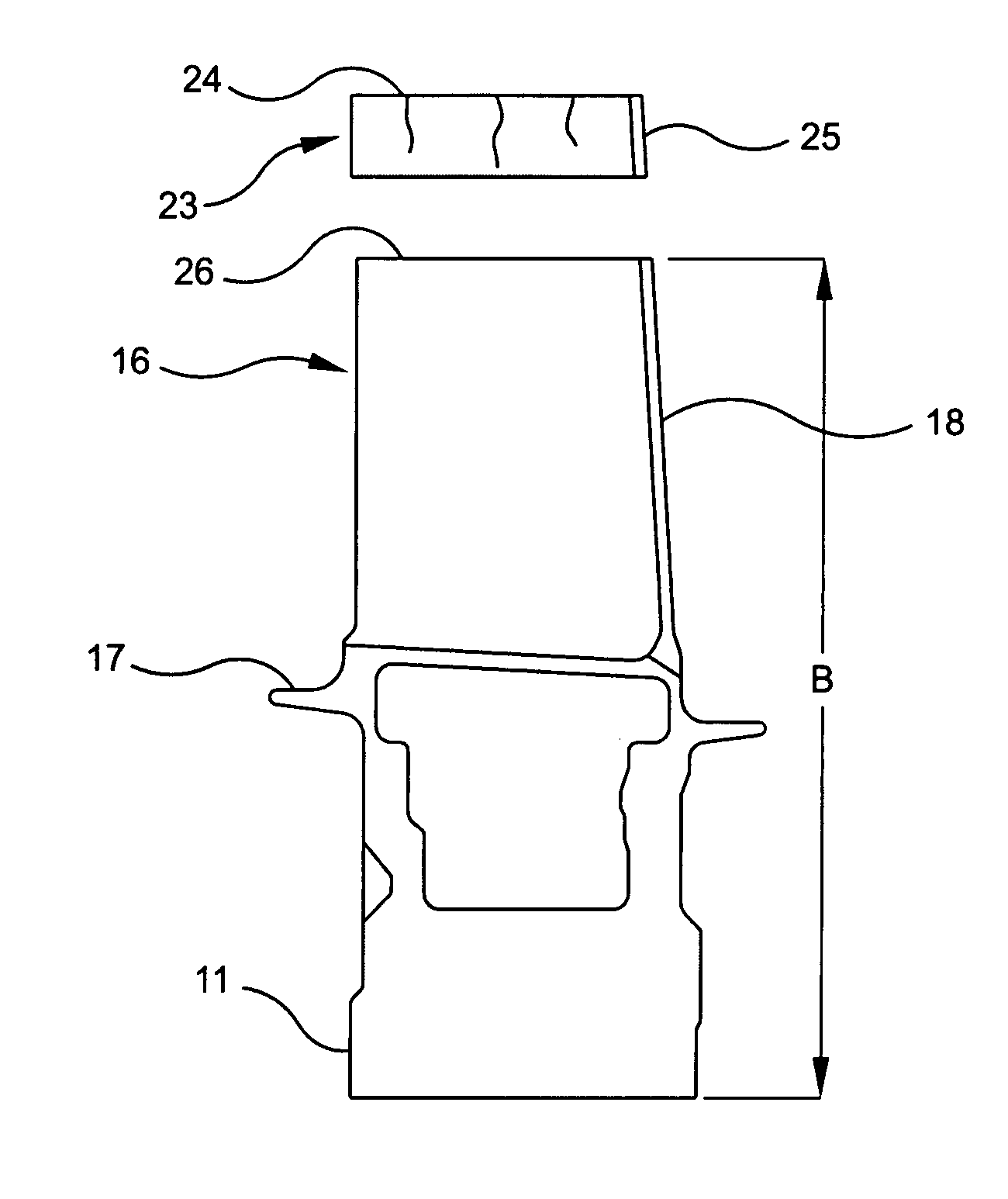
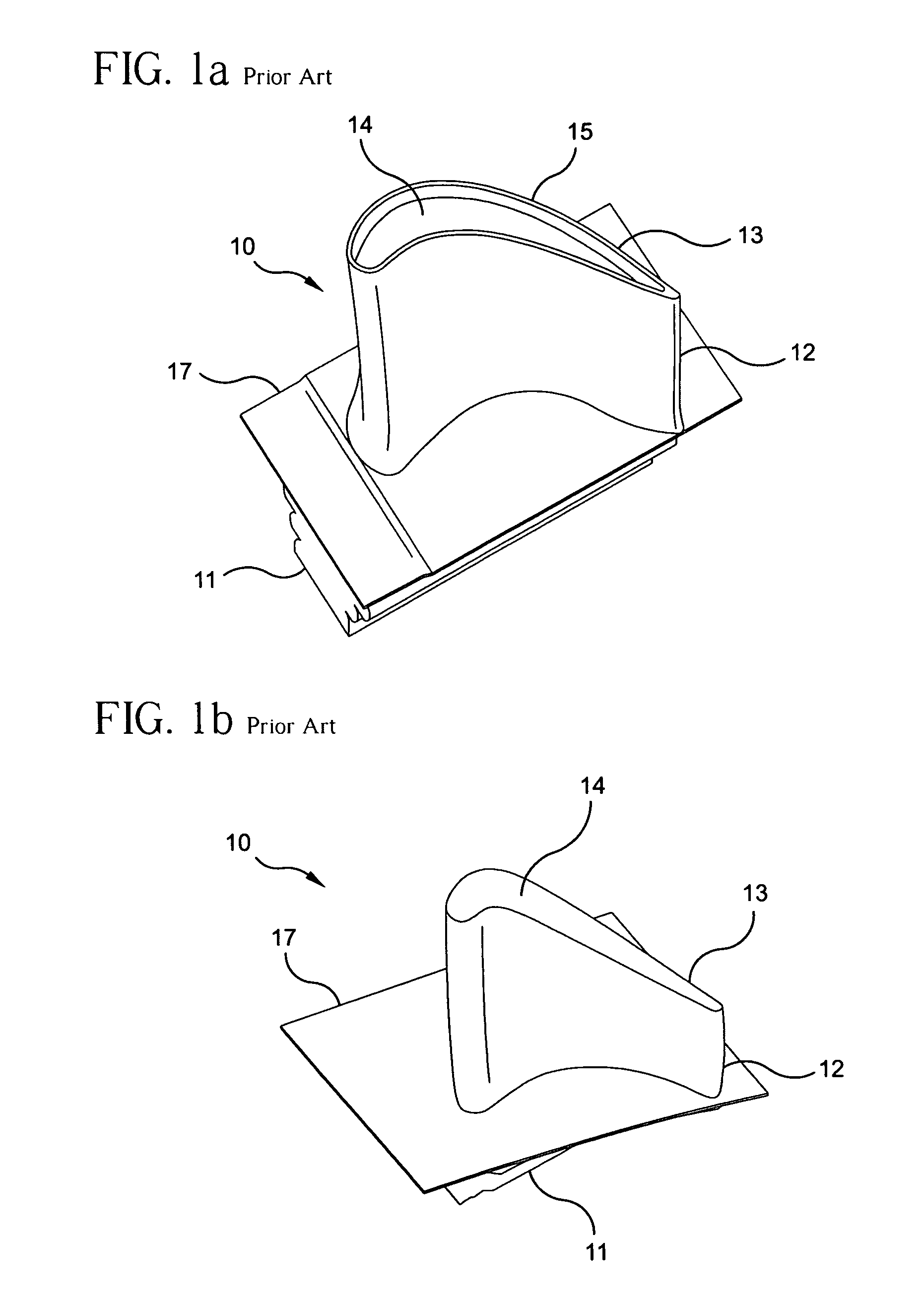
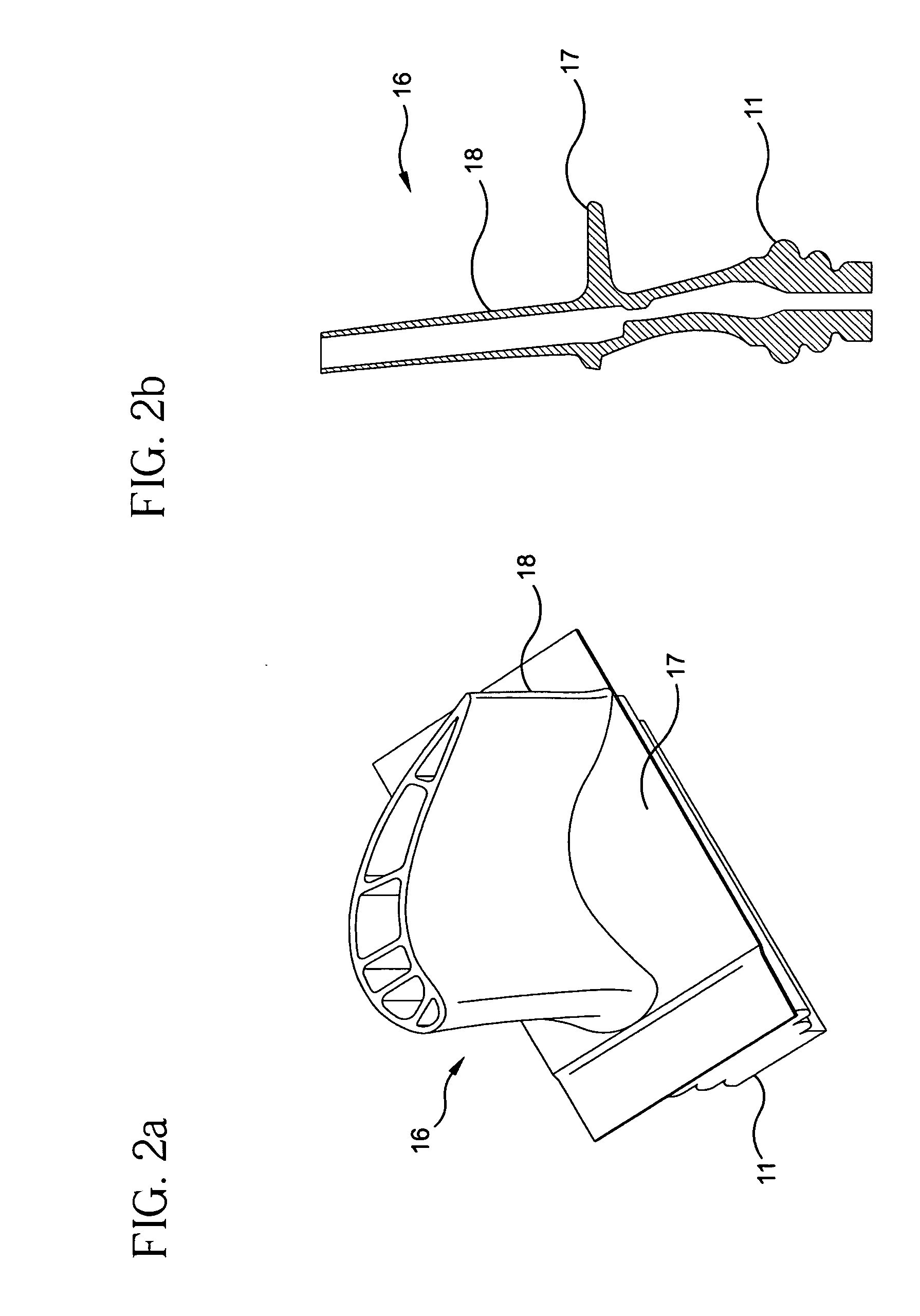
[0025] In accordance with this invention a turbine blade, a method of manufacture of a turbine blade and a method of repair of a turbine blade is provided. In FIGS. 2-7 a newly manufactured or repaired turbine blade 10 is shown which is made of at least two pieces and generally comprises a blade body 16 and a tip section 19. The blade body has a blade root 11, a blade platform 17 and a first airfoil portion 18. The tip section 19 has a tip cap 20 and a second airfoil portion 21. In one embodiment as shown in FIGS. 3a, 3b, 5a and 5b the tip cap 20 also has a squealer tip 22. The newly manufactured or repaired blade is an assembly of the blade body 16 and tip section 19 using a suitable bonding method such as thermal or thermo-mechanical diffusion bonding, brazing, welding, etc.

[0026] When a new blade is made in accordance with the invention, the blade body 16 is manufactured without any tip cap (see FIGS. 2a and 2b). The blade body 16 is produced slightly longer than needed. No spec...


PUM

PropertyMeasurementUnit
lengthaaaaaaaaaa
lengthaaaaaaaaaa
thermalaaaaaaaaaa

Abstract

A turbine blade and a process for manufacture of turbine blades is provided comprising: casting as one piece a blade body and a first portion of an airfoil; forming a tip section having a tip cap and a second portion of an airfoil which is sized to fit on the first portion of the airfoil; and attaching the first portion of the airfoil to the second portion of the airfoil. A process for repairing turbine blades is provided which comprises: removing the tip cap and a portion of the airfoil from the blade to form a repair surface on the airfoil; forming a replacement tip section comprising a replacement tip cap and a replacement portion of the airfoil sized to fit onto the repair surface; and attaching the replacement tip section to the repair surface.

Description

BACKGROUND OF THE INVENTION [0001] This invention relates to turbine blades for gas turbine engines and the manufacture of a turbine blade having a blade body and a separately formed tip section and more particularly wherein the blade body comprises a first portion of the airfoil and the tip section comprises a tip cap and a second portion of the airfoil. This invention further provides for the repair of a turbine blade by removal of the tip cap and a portion of the airfoil and forming and attaching a replacement tip section comprising a replacement tip cap and a replacement portion of the airfoil. [0002] Turbine blades have different operation requirements which apply to different areas of the blade. The blade tip cap has to resist rubbing, has to be more oxidation resistant then the blade airfoil and does not carry large centrifugal or bending loads (no benefit for directionally solidified or single crystal structure). The blade airfoil does not need to resist rubbing, carries lar...

Claims


Application Information

Patent Timeline
Patent Type & Authority Applications(United States)
IPC IPC(8): B23P6/00B23P15/04F01D5/00
CPCB23P6/005B23P15/04F01D5/005Y10T29/4973F05D2230/234F05D2230/80Y10T29/49318F05D2230/21
Inventor NENOV, KRASSIMIR P.SAMRETH, ARNOLD S.VANDYOUSSETI, MEHRDAD
Owner CHROMALLOY GAS TURBINE
Why Eureka
Try Eureka