Method and apparatus for controlling gas flow through granulate in drying hoppers

Active Publication Date: 2005-05-05
GRAEFF RODERICH W
View PDF10 Cites 16 Cited by
  • Summary
  • Abstract
  • Description
  • Claims
  • Application Information

AI Technical Summary

Benefits of technology

[0013] In an additional advantageous arrangement in accordance with the invention the use of a second temperature sensor can be avoided. This is based on the realization that the temperature of the return air fluctuates widely. Whenever heated granulate is continuously taken out of the bottom of the drying hopper and replenished by the batch wise addition of granulate to be heated at the top of the hopper, the temperature of the return air falls off for a short time quite strongly when granulate is being added, practically to the temperature of the just added granulate. Then the granulate gets s

Problems solved by technology

Especially when heating and drying granulates in drying hoppers where the granulate is continually taken out at the bottom with a desired temperature and the granulate to be dried is added batch wise at the top of the hopper, it is very difficult to reach an optimal gas throughput.
This results in great losses of energy.
If the gas flow is unnecessarily large additional losses of energy are encountered when the return gas coming from the drying hopper flows through a drier for the elimination of its moisture content and from there after being reheated to the drying temperature in a closed circuit back to the bott

Method used


Image

  • Method and apparatus for controlling gas flow through granulate in drying hoppers
  • Method and apparatus for controlling gas flow through granulate in drying hoppers
  • Method and apparatus for controlling gas flow through granulate in drying hoppers

Examples


Embodiment Construction

[0019] In the following description and the drawings, equivalent parts show the same reference numbers.

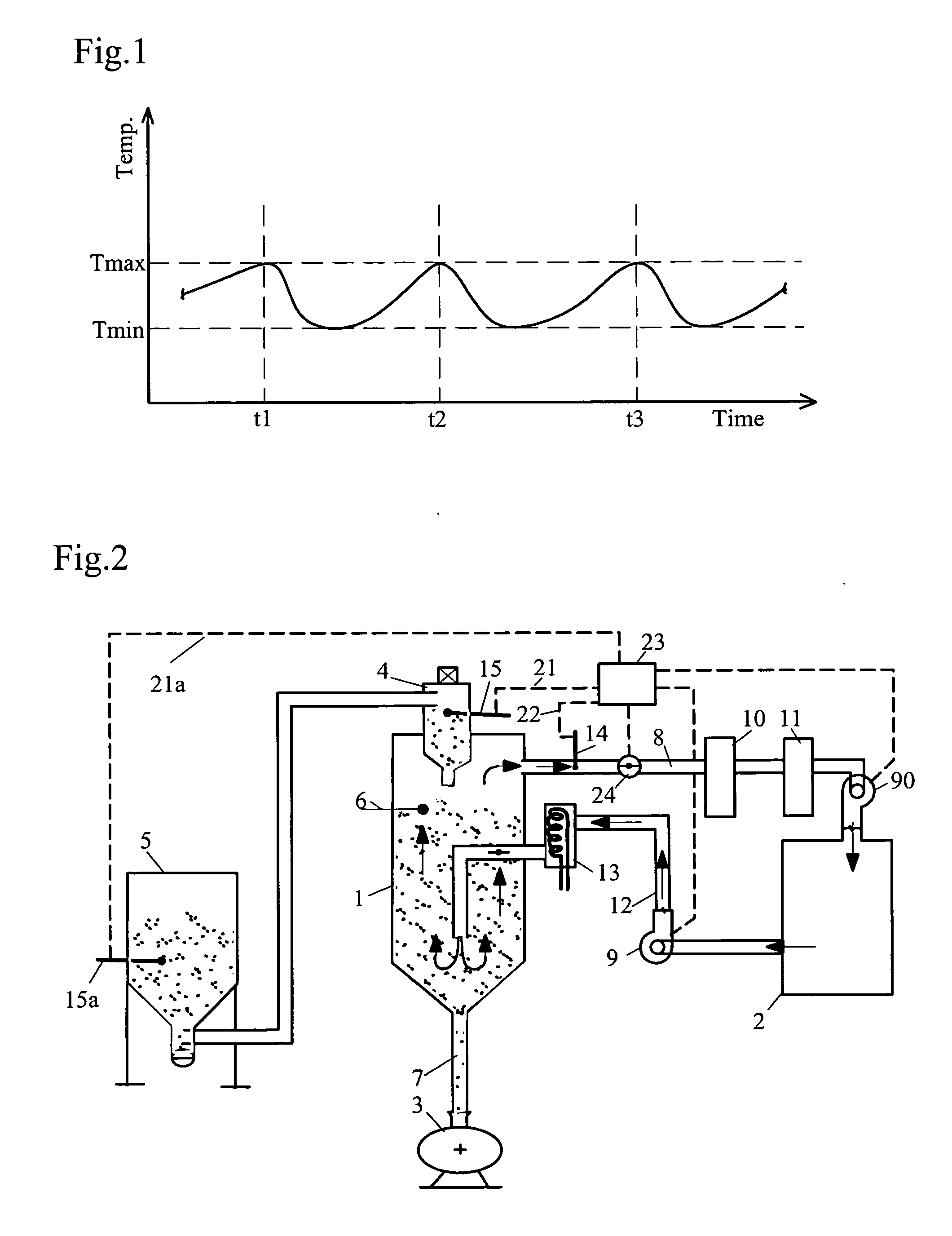
[0020]FIG. 1 shows the changing temperature of the return air over time. At the times 1, 2 and 3 a batch of granulate was added at the top of the drying hopper. In consequence of this the temperature of the return air falls to a minimum, which practically corresponds to the temperature of the added granulate. Then the temperature slowly increases following the slow heating of the added granulate up to a maximum when new granulate is added once again.

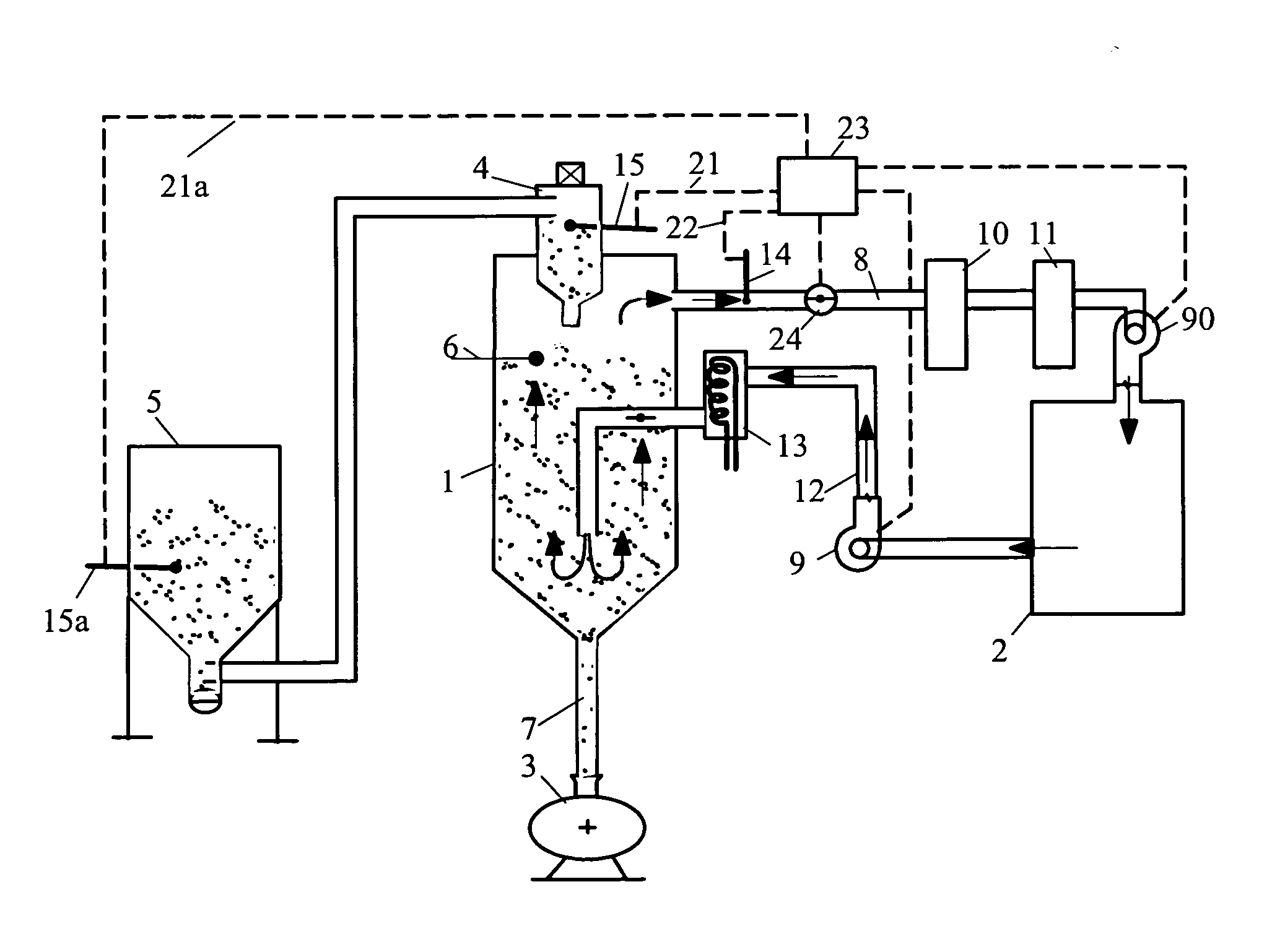
[0021]FIG. 2 shows a dryer (2), representing an adsorption or refrigeration dryer. The granulate hopper (1) has a conveyer unit (4) at the top which sucks granulate out of granulate container (5) and lets it drop into granulate hopper (1) whenever level sensor (6) demands it. Dried granulate leaves the granulate hopper via duct (7) to a fabricating machine (3).

[0022] Return air leaves the hopper (1) via duct (8), sucked by blower (9)...


PUM

PropertyMeasurementUnit
Temperatureaaaaaaaaaa
Timeaaaaaaaaaa
Pressureaaaaaaaaaa

Abstract

Method and apparatus for drying granulate material in a hopper by controlling the amount of gas which flows through the hopper to heat and to dry the granulate. The control allows to use a minimum amount of gas for heating the granulate to the drying temperature and to dry it with an optimal low energy consumption. This effect is reached by controlling the amount of gas flowing through the drying hopper as a function of the temperature difference between the temperature of the heating gas leaving the drying hopper and the granulate to be heated.

Description

BACKGROUND OF THE INVENTION [0001] 1. Field of the Invention [0002] The invention pertains to the field of gas flow control. More particularly, the invention pertains to control of gas flow in drying hoppers. [0003] 2. Description of Related Art [0004] Especially when heating and drying granulates in drying hoppers where the granulate is continually taken out at the bottom with a desired temperature and the granulate to be dried is added batch wise at the top of the hopper, it is very difficult to reach an optimal gas throughput. Therefore it is common to choose a gas flow much too high just to be sure that all of the granulate gets really heated to the desired final temperature. This results in great losses of energy. [0005] If the gas flow is unnecessarily large additional losses of energy are encountered when the return gas coming from the drying hopper flows through a drier for the elimination of its moisture content and from there after being reheated to the drying temperature ...

Claims


Application Information

Patent Timeline
IPC IPC(8): B01D53/26F26B3/16F26B5/16F26B9/06F26B17/14F26B21/08F26B21/12F26B25/00
CPCF26B9/063F26B21/12F26B21/08F26B17/14B29B9/16B29B13/065B29B7/826B29B7/60
Inventor GRACFF, RODERICH W.
Owner GRAEFF RODERICH W
Why Eureka
Try Eureka